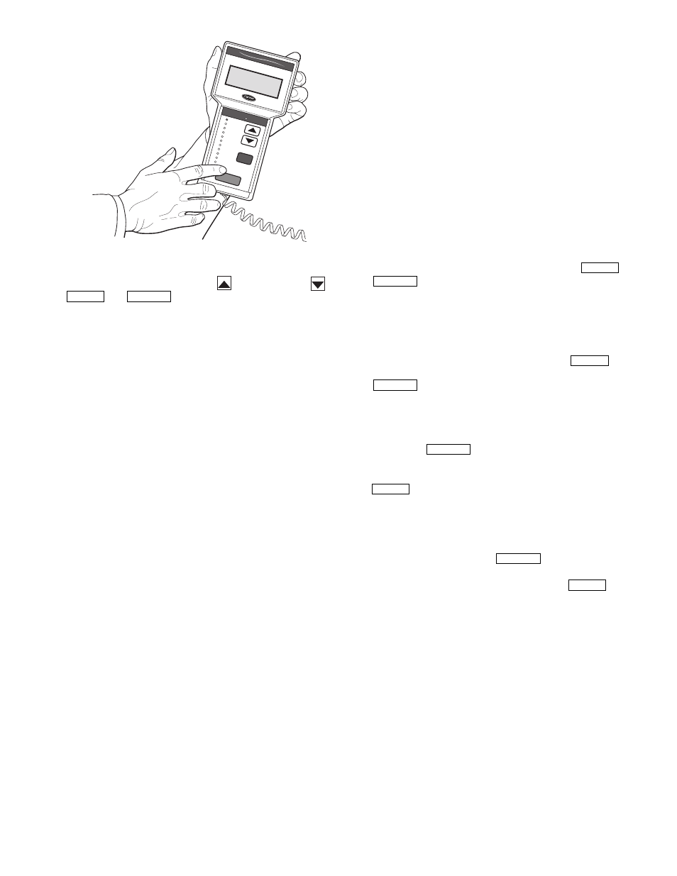
Fig. 31 — navigator™ module in display mode – Carrier PREMIERLINK 33CSPREMLK User Manual
Page 27
27
keys which are the up arrow (
), down arrow (
),
and
keys.
INSTALLATION — The Navigator display module is intend-
ed to be a mobile device, so there are no holes in the device for
permanent mounting. The module has a magnetic mount that is
strong enough to hold the device in place on any clean, dry
metal surface.
To enter LEN (local equipment network) mode:
1. Remove power by removing connection to J1.
2. Remove connection to J2 (to avoid communication prob-
lems with equipment).
3. Position DIP switch to 0 (ON) position.
4. Restore power by reconnecting J1.
5. Plug in Navigator.
Controller is now in LEN mode and will support the
Navigator device.
To return CCN mode:
1. Remove power to controller by removing connection
to J1.
2. Remove connection to J2 (to avoid communication
problems with equipment).
3. Position DIP switch to 1 (OFF) position.
4. Reconnect J2.
5. Restore power by reconnecting J1.
Controller is now in CCN mode at the previously config-
ured address and baud rate.
The Navigator module is powered through the PremierLink
controller. The Navigator has a modular telephone style (RJ14)
connector and should be connected to terminal block TB3 in
the control box. This device is intended for use on the LEN
communications bus only. Do NOT connect to the Navigator
while in CCN mode. Communication problems may occur.
OPERATION — To use the Navigator, plug the RJ14 connec-
tor into the RJ14 port. On power up, the Navigator displays:
PremierLink
Navigator
By
Carrier
The Navigator will upload the appropriate display tables
from PremierLink™ controller. A ‘Communication failure’
message will be displayed if any errors are encountered. Check
the wiring at the connector. After successful upload of informa-
tion, the Navigator begins its default display. All items in the
Run Status menu are displayed one at a time in this mode. An
example of the display in the default mode is:
SAT 54.2 °F
SUPPLY AIR TEMPERATURE
The different levels of modes can be accessed with the
Navigator. See the base unit controls and troubleshooting guide
for more information.
Pressing any key while in the default display mode will
cause the Navigator to enter its manual mode. In this mode, all
sub-modes and items within the eleven top level configuration
modes, denoted on the display screen, can be accessed. The
Navigator automatically returns to the default display mode af-
ter 60 minutes of no keypad activity. Pressing the
and
keys simultaneously while the unit displays “Select
a menu item” will also log the device out and return it to its de-
fault display mode.
NAVIGATING THROUGH MENU STRUCTURES — The
arrow keys are used to scroll up and down to select sub-modes
within a mode or items within a sub-mode. See the base unit
troubleshooting guide for menu structure. The
key is
used to select a menu item or to accept data entry. The
key is used to exit to the next highest mode or to
cancel data entry. The sub-mode and item displays will wrap
around with the last and first items separated by a line of dashes
on the display. The ‘>’ symbol is the pointer and is located at
the left side of the display.
Press the
key to display “Select a menu item” on
the screen. This is the top level and the arrow keys are used to
move the red LED to the one of the 11 desired modes. Pressing
will display the sub-modes within a top level mode.
Once in a sub-mode, use the arrow keys to move the pointer
(‘>’) to the desired sub-mode. Up to four sub-modes will be
displayed on the Navigator at one time. Continue pressing the
arrow keys as needed to find the desired sub-mode.
As an example, Press the
key to display “Select
a menu item” on the screen. Press the down arrow until the red
LED is lit for the Setpoints menu. Press the
key to
display the first four sub-modes in the Setpoints menu:
>SETP
OATL
NTLO
UHDB
ENTER
ESCAPE
ENTER
ESCAPE
ENTER
ESCAPE
ESCAPE
ENTER
ESCAPE
ENTER
Run S
tatus
Service T
est
Temperatu
res
Pressure
s
Setpoints
Inputs
Outputs
Configuration
Time C
lock
Operating M
odes
Alarm
s
E NTE
R
E S C
M O D
E
Alarm Status
TIME
EWT
LWT
SETP
1 2 . 5 8
5 4 . 6 °F
4 4 . 1 °F
4 4 . 0 °F
N A V
I G A
T O R
C o m f o
r t
L i n k
Fig. 31 — Navigator™ Module in Display Mode