Internal piping connections, 7 internal piping connections – B&C Technologies IM Series Industrial Ironer User Manual
Page 30
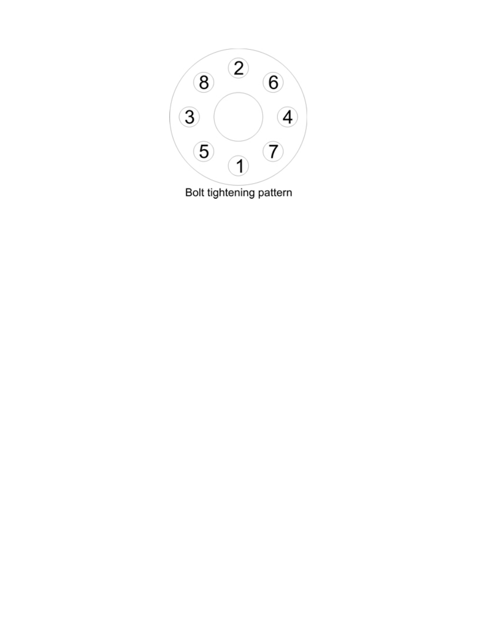
Figure 3.4: Thermal Fluid Flange Bolt Tightening
edge of the chest. The endframes must rest firmly on the floor.
• After the modules are set in location, bolt the lower I-Beams together using the hex bolts
(M20 x 50). Do not tighten the bolts yet.
• Bolt the upper connecting brackets between the modules using the hex bolts (M8 x 35). Do
not tighten the bolts yet.
• Level the modules by using sheet metal shims. The shims are to be used only under I-Beam
at the chest support. The modules are to be leveled horizontally in two directions and must
be parallel to each other.
• The holes for the roll pins (8 x 25) are drilled while the ironer is preassembled at the factory.
Now tighten all bolts using the following torque values: (M8 = 16 ft-lb / 22 Nm) (M20 = 300
ft-lb / 420 Nm)
3.5.7
Internal Piping Connections
Once all modules are aligned, secured, and bolted together, the thermal fluid piping must be con-
nected.
Starting at the rear module, connect the thermal fluid piping to the next module using the gaskets
and bolts provided. Use care to avoid damaging the gaskets during installation.
Tighten the nuts and bolts by hand, then follow the crisscross pattern shown in figure 3.4.
Repeat these steps for each additional module.
After all internal thermal fluid piping has been connected, recheck for level on all modules using
a large carpenters level.
20