B&C Technologies IM Series Industrial Ironer User Manual
Page 133
7
INSTALLATION
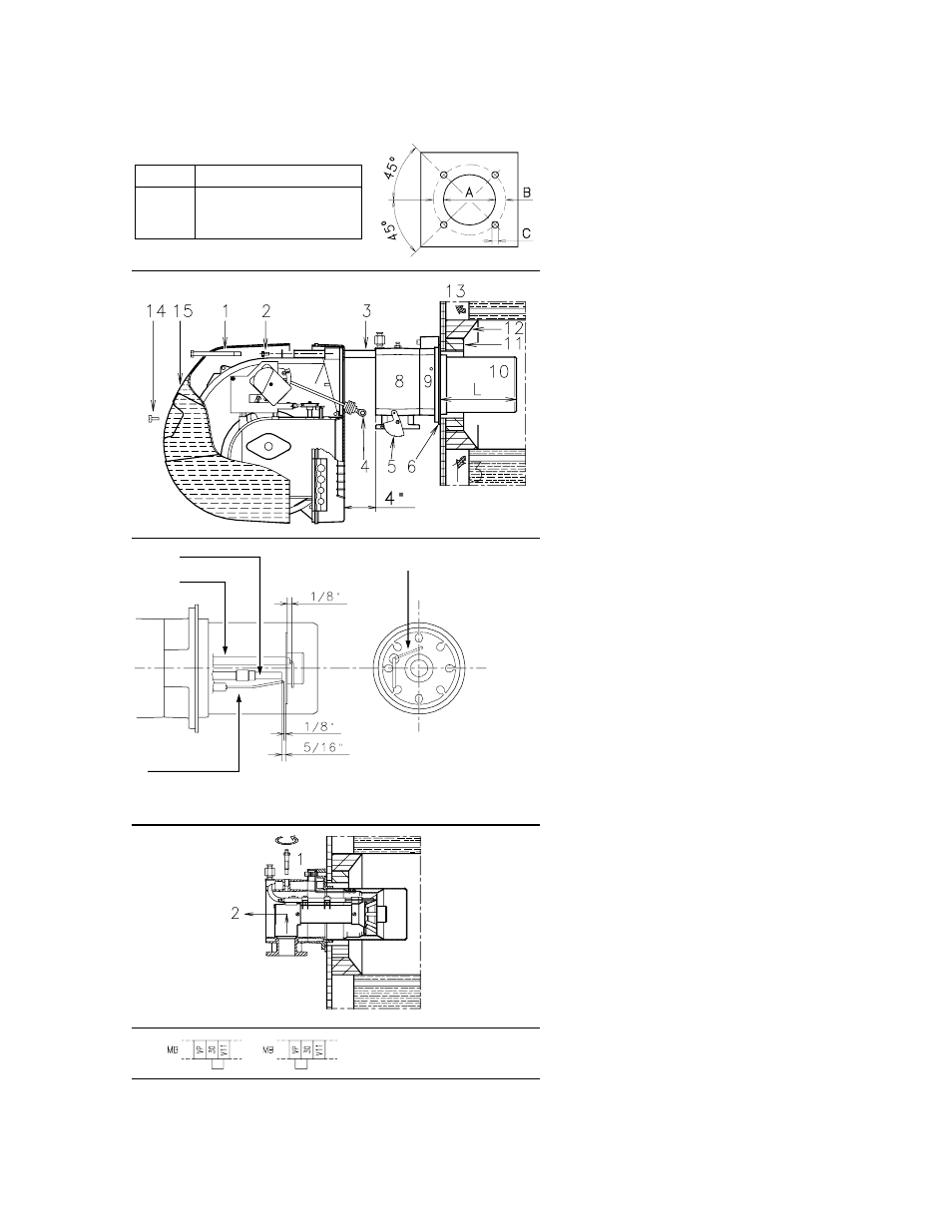
BURNER MOUNTING (A)
Drill the combustion chamber mounting plate as shown
in (A).
The position of the threaded holes can be marked using
the head gasket supplied with the burner.
BLAST TUBE LENGTH (B)
The length of the blast tube must be selected according
to the indications provided by the manufacturer of the
boiler, and it must be greater than the thickness of the
boiler door complete with its insulation. The range of
lengths available, L (inches), is as follows:
Blast tube 10): RS 28/M
RS 38/M
RS 50/M
• short
8
1/2
”
8
1/2
”
8
1/2
”
• long
13
13/16
”
13
13/16
”
13
13/16
”
For boilers with front flue passes 13) or flame inversion
chambers, protective insulation material 11) must be
inserted between the boiler refractory 12) and the blast
tube 10).
This protective insulation must not compromise the
extraction of the blast tube.
For boilers having a water-cooled front, the insulation
11)-12)(B) is not required unless it is required by the
boiler manufacturer.
SECURING THE BURNER TO THE BOILER (B)
Before securing the burner to the boiler, check through
the blast tube opening to make sure that the flame sen-
sor probe is correctly set in position, as shown in (C).
Now detach the combustion head from the burner,
fig.(B):
- Remove screw 14) and withdraw the cover 15).
- Disengage the swivel coupling 4) from the graduated
sector 5).
- Remove the screws 2) from the slide bars 3)
- Remove screw 1) and pull the burner back on slide
bars 3) by about 4”.
Disconnect the wires from the probe and the elec-
trode and then pull the burner completely off the slide
bars, after removing the split pin from the slide bar 3).
Secure the flange 9)(B) to the boiler plate, inserting the
head gasket 6)(B). Use the 4 screws, also supplied with
the unit, after first protecting the thread with an anti-seize
product.
The seal between burner and boiler must be airtight.
If you noticed any irregularities in the positions of the
probe or ignition electrode during the check mentioned
above, remove screw 1)(D), extract the internal part
2)(D) of the head and set up the two components cor-
rectly.
IGNITION PILOT ADJUSTMENT
Place the pilot and electrode as shown in fig. (C).
The pilot works correctly at pressures ranging from 5 -
12” WC.
Important
To set the pilot without main burner operation, proceed
as follows:
- Move the jumper from terminals "
30-V11" to terminals
"
30-VP", as given in fig. (E), this way the main valve is
not energized.
- With the burner in the manual position, hold the air
damper in the minimum position and make the setting.
- When the setting is correct, replace the jumper on “
30-
V11”.
(C)
inch
A
B
C
RS 28/M
6
9/32
“
8
13/16
“
3/8
W
RS 38/M
6
9/32
“
8
13/16
“
3/8
W
RS 50/M
6
9/32
“
8
13/16
“
3/8
W
D455
(A)
(D)
D2260
(B)
D2292
D2261
(E)
MB - Burner terminal strip
D2317
Probe
Electrode
Ignition pilot
TOP VIEW
SIDE VIEW
Probe position
123