Etanorm sya – B&C Technologies IM Series Industrial Ironer User Manual
Page 105
1215:6/2
F
V
F
H
F
H
F
H
F
H
F
V
+
+
1
2
2
2
L
Caution
Etanorm SYA
6
4.4
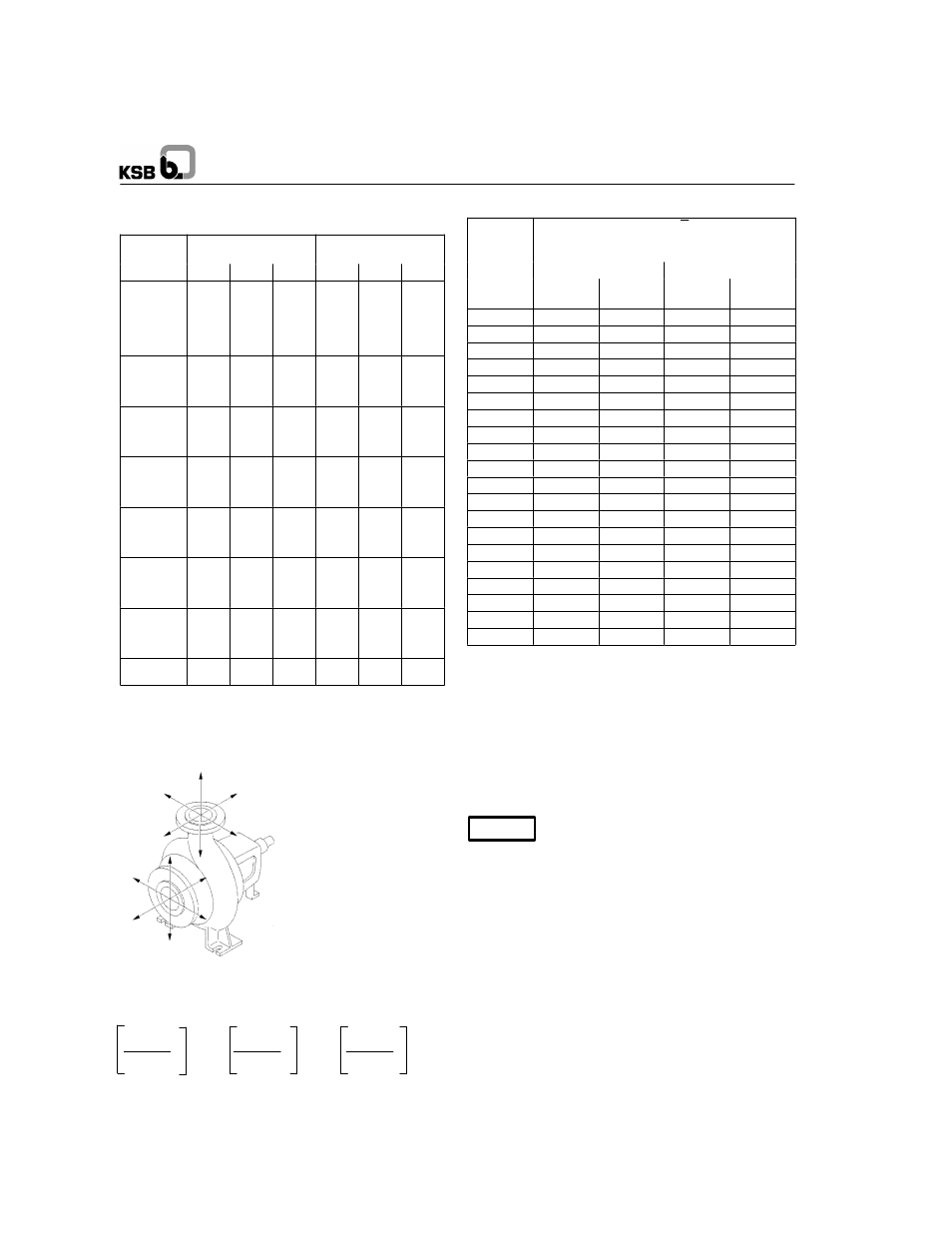
Permissible Forces and Moments at the Pump
Nozzles
Etanorm
SYA
t = 20
C
F
Vmax
F
Hmax
M
tmax
t = 300
C
F
Vmax
F
Hmax
M
tmax
[kN]
[kN]
[kNm]
[kN]
[kN]
[kNm]
32-125.1
32-160.1
32-200.1
32-160
32-200
32-250
3.65
3.56
3.60
3.56
3.65
3.65
2.59
2.51
2.43
2.51
2.43
2.43
0.58
0.51
0.51
0.51
0.51
0.51
3.15
3.08
3.11
3.08
3.11
3.11
2.24
2.17
2.10
2.17
2.10
2.10
0.50
0.44
0.44
0.44
0.44
0.44
40-160
40-200
40-250
40-315
3.81
3.81
4.21
4.09
2.67
2.67
2.92
2.84
0.81
0.81
0.58
0.55
3.29
3.29
3.64
3.54
2.31
2.31
2.52
2.46
0.70
0.70
0.50
0.48
50-160
50-200
50-250
50-315
3.97
4.21
4.58
4.54
2.67
2.92
3.32
3.24
1.11
1.11
0.87
0.84
3.43
3.64
3.96
3.92
2.31
2.52
2.87
2.80
0.96
0.96
0.75
0.73
65-160
65-200
65-250
65-315
4.42
5.27
5.27
5.43
3.04
3.89
3.89
4.05
1.16
1.79
1.79
1.62
3.82
4.55
4.55
4.69
2.63
3.36
3.36
3.50
1.00
1.55
1.55
1.40
80-160
80-200
80-250
80-315
5.43
6.08
6.16
6.28
4.05
4.74
4.78
4.86
1.91
2.44
2.44
2.78
4.69
5.25
5.32
5.43
3.50
4.10
4.13
4.20
1.65
2.10
2.10
2.40
100-160
100-200
100-250
100-315
7.70
7.70
7.86
7.57
6.28
6.28
6.48
6.16
3.60
3.60
3.47
3.18
6.65
6.65
6.79
6.54
5.43
5.43
5.60
5.32
3.10
3.10
3.00
2.75
125-200
125-250
125-315
125-400
9.50
9.84
9.32
9.23
8.50
8.71
8.10
7.90
5.10
5.10
4.75
4.63
8.21
8.50
8.05
7.97
7.34
7.53
7.00
6.83
4.40
4.40
4.10
4.00
150-315
150-400.1
10.53
10.53
9.72
9.72
5.67
5.67
9.10
9.10
8.40
8.40
4.90
4.90
The
values
indicated
apply
to pumps
made
of nodular
cast iron
JS 1025
3)
.
3) to EN 1563 = GJS-400-18-LT
Fig. 4.4-1 Forces and moments at the pump nozzles
The following condition must be met:
π
IF
V
I
π
IF
H
I
π
IM
t
I
IF
Vmax
I
IF
Hmax
I
IM
tmax
I
π
IF
V
I,
π
IF
H
I and
π
IM
t
I are the sums of the absolute values
of the respective loads acting on the nozzles. These sums
neither take into account the direction of the forces and mo-
ments nor their distribution among the nozzles.
4.5
Noise Characteristics
Rated
power
input P
N
Surface sound pressure level
pA
Pump only
Pump with motor
(kW)
1450 1/min
dB
1)
2900 1/min
dB
1)
1450 1/min
dB
2)
2900 1/min
dB
2)
0,55
46
48
50
56
0,75
48
50
52
58
1,1
50
52
55
60
1,5
51
53
56
62
2,2
53
55
58
64
3,0
55
57
60
66
4,0
57
59
62
67
5,5
58
60
63
69
7,5
60
62
65
70
11,0
62
64
66
72
15,0
63
66
68
74
18,5
64
67
69
75
22,0
65
68
70
75
30,0
67
69
71
77
37,0
68
71
72
77
45,0
69
72
73
78
55,0
70
73
73
79
75,0
72
74
75
80
90,0
73
75
75
80
110,0
74
76
76
81
1) Measured at a distance of 1 m from the pump outline
(to DIN 45 635 part 1 and 24)
2) Measured at a distance of 1 m from the complete unit outline
(to DIN 45 635, part 1 and 24)
The above noise characteristics apply to non-cavitating pump
operation in the Q
opt.
range.
4.6
Accessories
Drive
Surface cooled IEC three phase squirrel cage motor
When the pump is driven by an electric
motor, the motor’s cooling air must flow
in axial direction towards the pump end.
Air velocity
∫∫∫∫
3 m/s, measured at the
drive side bearing end plate. When the
pump is driven by an I.C. engine, only
such air-cooled engines shall be used
whose cooling air is drawn in and dis-
charged over the coupling/flywheel.
Coupling
Design:
Flexible coupling with or without spacer
Baseplate:
Channel section steel or folded steel plate
for the complete unit (pump and motor) in
torsion-resistant design
Drive, coupling and baseplate can be supplied by KSB or the
operator.
95