B&C Technologies IM Series Industrial Ironer User Manual
Page 143
17
(B)
(A)
ELECTRICAL SYSTEM
ELECTRICAL SYSTEM as set up by the manufacturer
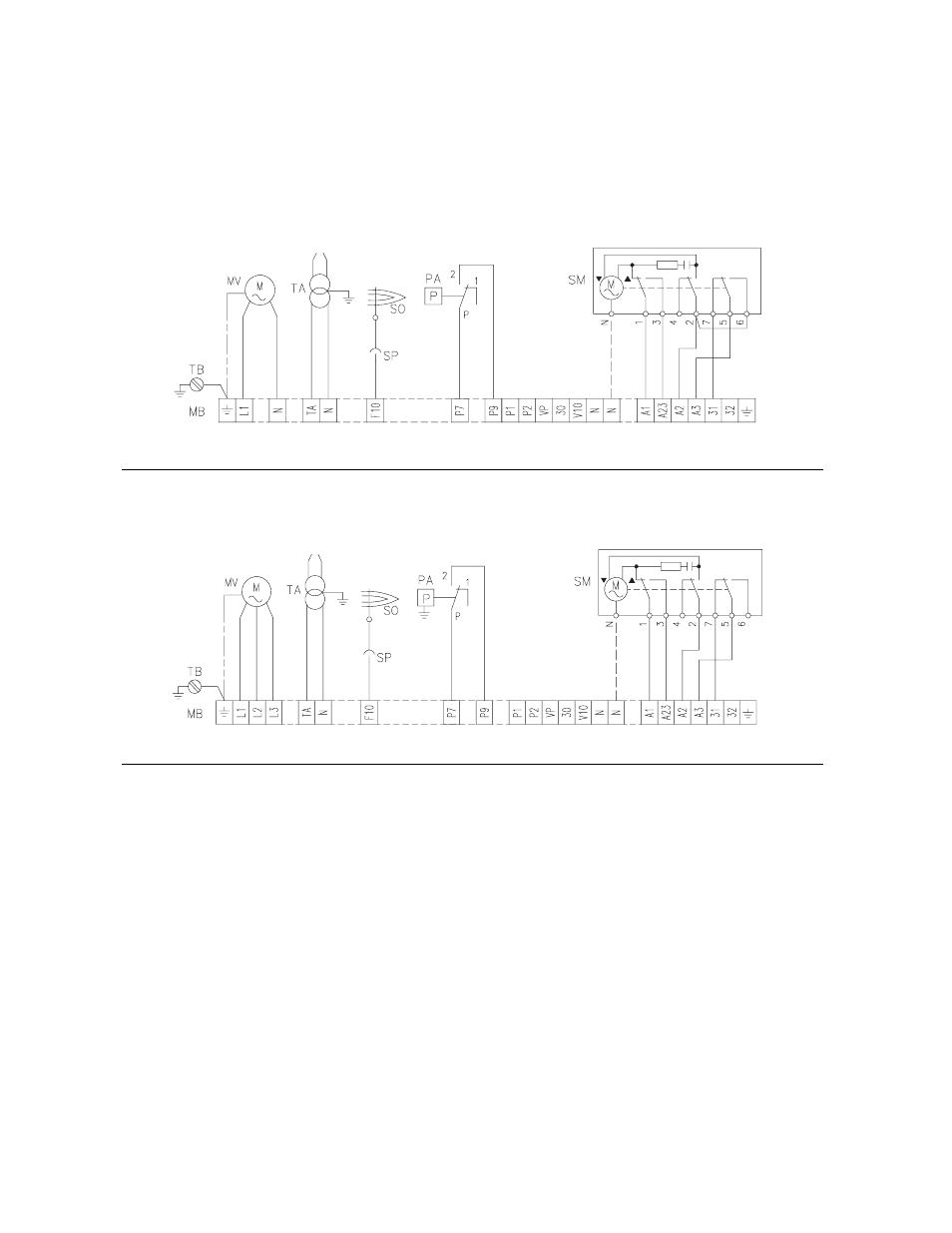
LAYOUT (A)
Burner RS 28/M - RS 38/M (single-phase)
The flame safeguard is in remote panel.
See the internal electrical systems of the remote panel in order to
have the complete wiring diagram.
LAYOUT (B)
Burners RS 38/M - RS 50/M (three-phase)
The flame safeguard is in remote panel.
See the internal electrical systems of the remote panel in order to
have the complete wiring diagram.
Key to Layouts (A) - (B)
C
- Capacitor
CMV
- Motor contactor
DA
- Siemens LFL Control box
MB
- Burner terminal strip
MV
- Fan motor
PA
- Air pressure switch
RT
- Thermal overload
S1
- Switch for following operations:
MAN = manual
AUT = automatic
OFF
S2
- Button for:
- = power reduction
+ = power increase
SM
- Servomotor
SO
- Ionisation probe (flame rod)
SP
- Plug-socket
TA
- Ignition transformer
TB
- Burner ground
D2396
D2403
Factor Wiring Diagram
RS 28/M - RS 38/M single-phase with Remote Panel
Factory Wiring Diagram
RS 38/M - RS 50/M three-phase with remote panel
133