Connectors, controls, indicators, Front panel controls and indicators (see figure 1) – Welch Allyn AM 232 Manual Audiometer - User Manual User Manual
Page 11
11
12-16-08
Connectors, Controls, Indicators
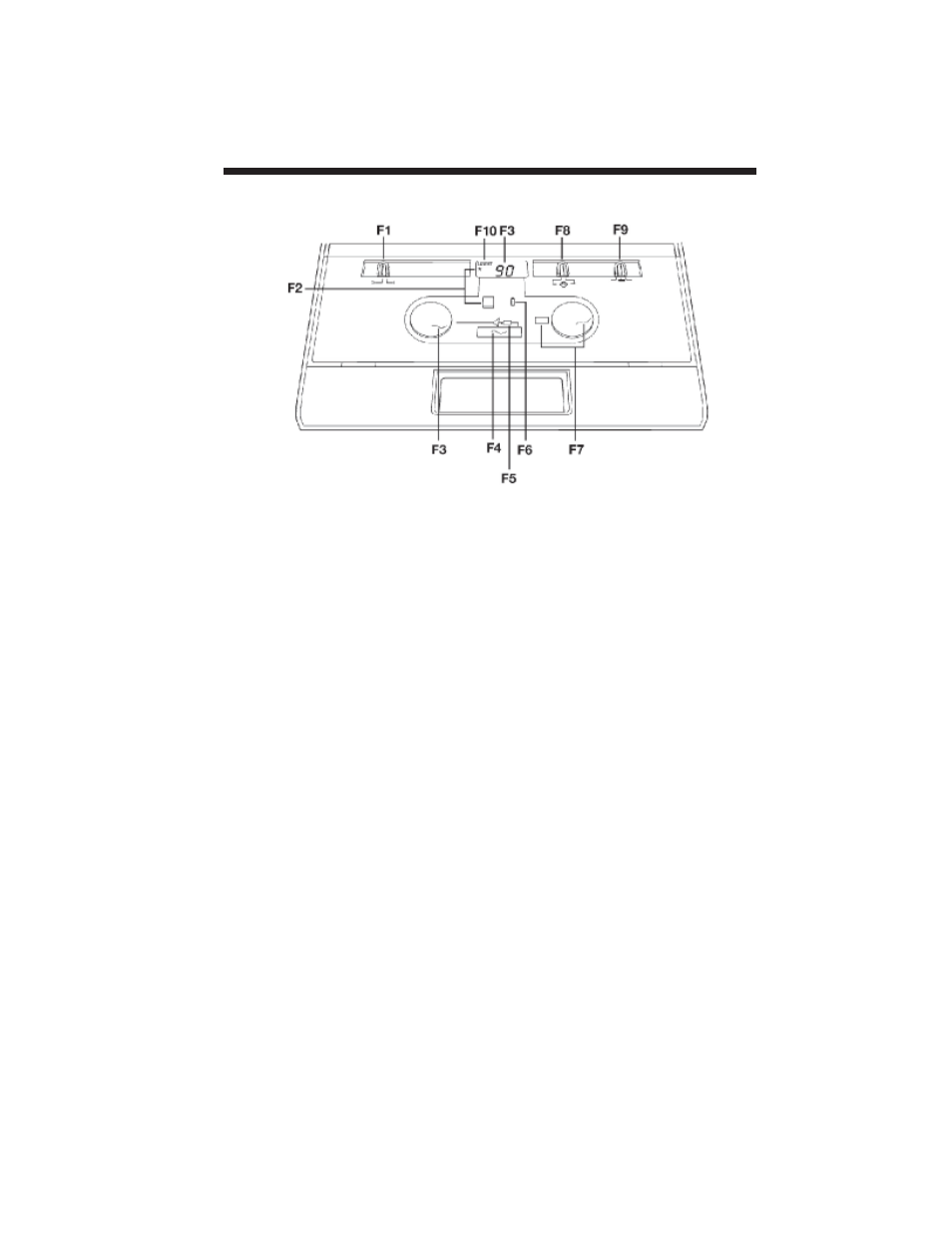
Figure 1: Front panel.
Front panel controls and indicators (see Figure 1)
F1 - Power switch and indicator for ON and OFF .
F2 - Range extension pushbutton allows you to increase the stimulus intensity 10 dB
above the standard maximum HL at any frequency. When in use, a “+” appears
on the LCD.
F3 - HL control for setting stimulus intensity level. Level is indicated on LCD.
F4 - Present bar for stimulus presentation.
F5 - Stimulus being presented via an earphone. Presentation indicated by illuminated
green LED.
F6 - Subject response indicator shows you when the test subject has pressed the
handswitch button by an illuminated green LED (with optional handswitch only).
F7 - Control for setting stimulus frequency. Frequency is indicated in the window
adjacent to the control.
F8 - Routing switch for stimulus presentation to the earphone. Left or right indicated
by illustration of subject.
F9 - Switch for setting the stimulus tone type.
FM = warble tone
__ = steady tone
- - - = pulsed tone
F10 - Low battery indicator to alert you of a limited operating time. Recharge or
replace batteries (dependent on whether NiCad or Alkaline batteries are used).