Installing the condensing unit – Vintage Cellars Platinum Split Fully Ducted 4000WC User Manual
Page 30
PSWC
033114
Page 28 | 1-800-343-9463
INSTALLING THE CONDENSING UNIT
Most water cooled units are installed indoors. Since this unit rejects all of its heat to a water source, there is no need
to provide special ventilation when installing indoors. If this unit is installed outdoors it must be installed in a location
which shelters it from adverse conditions such as direct sunlight and rain.
Using the mounting holes located in the base, fasten the condensing unit to a secure foundation.
o Purge the hoses with dry nitrogen and tighten the hose connections.
o Remove the service valve caps and turn the valve stem clockwise ½ turn to unseat the valve and open
the service port. Keep the piping ports sealed until ready to braze.
• Purge dry nitrogen through the fittings at a slow rate to prevent formation of highly abrasive copper oxide.
• Perform all brazes.
• Pressure test the system and check for leaks.
• Insulate the suction line using ½” wall cellular insulation or equivalent. Seal all seams with Armaflex 520 Foam
Insulation Adhesive or equivalent. Wrap each seam using line set tape.
Refrigerant Piping Overview
• Using the charts and illustrations found on the previous page, route the line set between the evaporator unit
and condensing unit. Be sure to reference the chart for correct line set sizing. All horizontal suction piping should
be pitched toward the condensing unit ½” for every 10’ of pipe. When installing and routing the line set, cap both
ends of each tube to prevent debris from entering the tubing.
• Prior to connecting the piping to the evaporator and condensing units, loosely connect a refrigerant manifold
to the suction and liquid line service valves.
Liquid Line Piping Procedure
• ¼” OD copper tubing is required for the liquid line on all systems.
• Flare a short piece of ¼” copper tubing.
• Remove the flare nut from the fitting on the liquid line valve.
• Slide the nut over the piece of tubing and attach the tubing to the fitting on the liquid line valve.
• Connect the supplied refrigerant drier to the tubing.
• Downstream from the drier, connect the moisture indicating sight glass in an easily visible location
• Run the tubing to the evaporator unit (fan coil unit) and attach to the liquid line connection on the evaporator
unit (fan coil unit).
Suction Piping Procedure
• Flare a short piece of 3/8” or ½” copper tubing. The correct size will depend on your model type.
• Remove the flare nut from the fitting on the suction line service valve.
• Slide the nut over the piece of tubing and attach the tubing to the fitting on the suction line service valve.
• Install an access valve close to the tubing and another at the outlet of the evaporator unit (fan coil unit).
• Run the pre-insulated suction line to the evaporator unit (fan coil unit) and attach to the suction line
connection on the evaporator unit (fan coil unit).
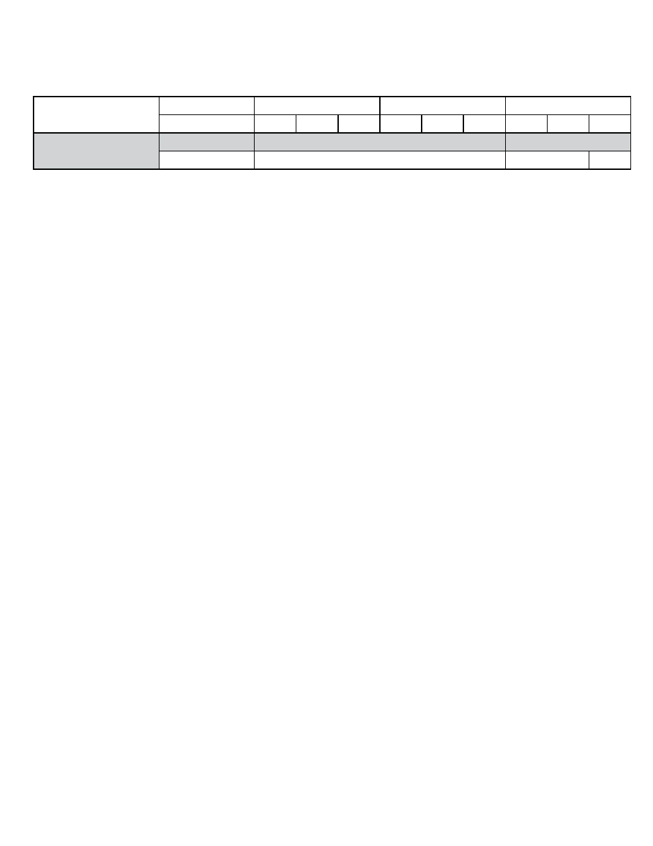
It is required to size the suction line tubing according to this chart.
The refrigerant drier and the sight glass shall be installed (in that order) in the direction of the refrigerant flow in the
liquid line between the condensing unit and Evaporator Unit (Fan Coil Unit). Enclose the suction line in a cellular
insulation ½” wall thickness Armaflex (brand name) or equal to reduce heat transfer.
Model
Line Set Length
<25ft
26-50ft
50-100ft
Vertical Rice
<3ft 3-10ft >10ft
<3ft 3-10ft >10ft
<3ft 3-10ft >10ft
Platinum Split 4000 WC
Horizontal Tubing
1/2”
5/8”
Vertical Rise
3/8”
5/8”
1/2”