Vintage Cellars Platinum Split Fully Ducted 4000WC User Manual
Page 14
PSWC
033114
Page 12 | 1-800-343-9463
INSTALLING THE WALL MOUNTED EVAPORATOR (FAN COIL UNIT)
9. Using 1/4” and 1/2” copper tubing, route the liquid and
suction lines through the knockouts in the wrapper. Be sure
to extend the tubing far enough outside of the wrapper
to extend through the wall if necessary. Note: ½” copper
tubing will slip over the 3/8” suction line on the evaporator
for an easy connection.
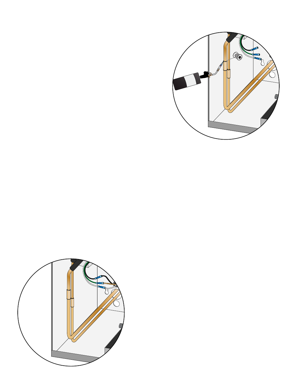
10. Remove the solenoid coil and wrap the solenoid valve with
a wet rag to prevent overheating.
11. To prevent oxidation, purge nitrogen through the system.
12. Braze the copper tubing to the connections on the
evaporator unit.
13. Insulate the suction line using Armaflex or similar insulation.
14. Cut a short piece of ½” drain line and connect a ½” barb 90
to the drain line.
15. Route the drain line out of the wrapper through the hole for the drain line. Use the second barb 90 if
going through the bottom of the wrapper. Be sure to extend the tubing far enough outside the wrapper
to extend through the wall if necessary.
16. Using the cable ties and cable tie mounts provided, secure the drain line to the bottom of the wrapper to
ensure a downward slope.
17. If you have purchased the Active Humidity Option, route the ¼” water line out of the evaporator unit
with the line set.
18. Route the power supply wires into the unit through the knockout.
19. Remove the wire nuts from the black, white and green wires located in the lower left corner of the
evaporator unit.
20. Following the supplied wiring diagram, connect the power supply wires to the black, white and green
wires using the supplied wire nuts (Hot=Black, Neutral=White, Ground= Green).
21. Install the supplied black strain relief to secure the power supply wires in the housing.
22. Route the display adapter through the grommet below
the drip dray and into the blower compartment.
23. Connect the display adapter to the circular connector for
the display located in the lower left corner of the housing.
24. If the unit was equipped with the Active Humidity Option,
route the communication cable from the desired control
mounting location into the evaporator unit.
25. Connect the communication cable to the circular
connector located in the lower left corner of the housing.
26. Secure all wiring neatly and close to the left wall to
minimize obstructing the airflow.
27. Attach the supplied bottle probe to the circular connector
on the bottom of the unit. Follow the directions on page
13 for correct installation and placement of the bottle
probe.
°
F
°
F