Max. vfd to cpc-3 lead length – Tjernlund CPC-3 Constant Pressure Controller Startup Manual 8504125 User Manual
Page 9
8
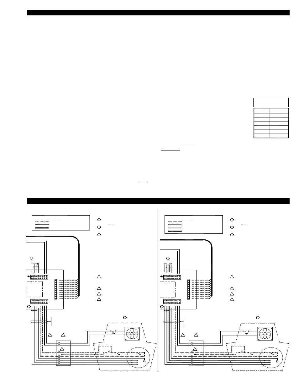
230 VOLT VSAD SERIES WIRING
460 VOLT VSAD SERIES WIRING
plate rating before applying power. Improper supply voltage
Verify that the input power voltage matches the VFD's name-
All wiring must be in metal conduit (best) or shielded cable.
the same conduit. Undesired VFD operation could result.
Do not run the VFD's input power and output power wiring in
Verify that the venter (VSAD 8/10/12-230) is rated for the
output voltage from the VFD. If not correct, severe damage to
3.
2.
1.
3.
2.
WARNINGS:
CAUTIONS:
1.
to the VFD could damage the VFD.
the venter and/or the VFD could result.
When the system is completely installed, perform the safety
interlock and operational test as outlined in the installation
4.
manuals. Failure to do these tests could result in an unsafe
and/or incorrectly operating system.
NOTES:
"C" means "Closed Loop"
"3" means "CPC-3 Control"
3
3
BLACK
VIOLET
ORANGE
GRN/YEL
BLUE
YELLOW
WHT/RED
RED
GRAY
WHT/BRN
VFD COMMUNICATIONS CABLE
A
DD F
O
R 208-230 V
A
C 3Ø
208-230 V
A
C 1Ø /
60 HZ
Route transducer wiring in metal conduit or use Belden Shield
Cable #9939 or equivalent. Make sure the transducer wiring
does not contain or cross line voltage wiring or undesired
Use caution to ensure that the wiring to the transducer is
Improper wiring to the transducer will destroy the transducer.
correct before activating the CPC-3 controller.
transducer performance may result.
4
For vertical termination of the VSAD venter, connect the S2
position to the orange wire and cap off the gray wire as shown.
For horizontal termination of the VSAD venter, connect the S2
position to the gray wire and cap off the orange wire.
4.
If the provided 10-foot, 10-wire VFD control cable is not long
1.
enough to meet the application needs, use caution to ensure
that the connections from the VFD to the CPC-3 controller
are correctly located. MB to MB, MC to MC, etc. In addition,
Use caulking to seal the electrical box cover to the electrical
2.
box, and to seal the conduit holes to hole plugs.
2
reference the Wire Length Table.
If required, non-fused disconnects are to be supplied by the
3.
installer.
3
FIGURE 8052017 11/18/04
INCLUDED
39" (1m) CABLE
BLACK
BLACK
ORANGE
BLUE
GREEN
VIOLET
RED
YELLOW
VSAD MOTOR ENCLOSURE
COOLING FAN
THERMOSTAT
FAN
GND
VERTICAL
TILT SWITCH
MOTOR
LIMIT
HIGH
LIMIT
L3
L2
L1
GRAY
BLK
BLK
BLK
BLK
BLK
BLUE
BLUE
WHT/BRN
HORIZONTAL
TILT SWITCH
BLK
WEATHERPROOF
BOX AND WHIP
MOTOR
Max. length:
dedicated metal conduit.
Wiring is to be in
230 VAC SUPPLY / LOAD WIRING
LEGEND:
LOW VOLTAGE / DC CONTROL WIRING
300' (91m) @ 230 VAC
TJERNLUND DRIVE MODEL
VFD- _ _ _ _ _ _ _ 2C3
"2" means "230 VAC"
2
VFD
CONTROL
BOX
M1
M2
M3
MG
ND
S1
S2
F1
F2
GN
D
L1
L2/
N
L3
NC
NC
L
L
MB
MC
M1
M2
S1
S2
SC
S3
D-
D+
INCLUDED
39" (1m) CABLE
BLACK
BLACK
ORANGE
BLUE
GREEN
VIOLET
RED
YELLOW
VSAD MOTOR ENCLOSURE
COOLING FAN
THERMOSTAT
FAN
GND
VERTICAL
TILT SWITCH
MOTOR
LIMIT
HIGH
LIMIT
L3
L2
L1
GRAY
BLK
BLK
BLK
BLK
BLK
BLUE
BLUE
WHT/BRN
HORIZONTAL
TILT SWITCH
BLK
WEATHERPROOF
BOX AND WHIP
MOTOR
Max. length:
dedicated metal conduit.
Wiring is to be in
230 VAC SUPPLY / LOAD WIRING
LEGEND:
LOW VOLTAGE / DC CONTROL WIRING
100' (30m) @ 460 VAC
TJERNLUND DRIVE MODEL
VFD- _ _ _ _ _ _ _ 4C3
"4" means "460 VAC"
2
4
VFD
CONTROL
BOX
M1
M2
M3
MG
ND
S1
S2
F1
F2
GN
D
L1
L2/
N
L3
NC
NC
L
L
MB
MC
M1
M2
S1
S2
SC
S3
D-
D+
460 VAC SUPPLY / LOAD WIRING
plate rating before applying power. Improper supply voltage
Verify that the input power voltage matches the VFD's name-
All wiring must be in metal conduit (best) or shielded cable.
Route transducer wiring in metal conduit or use Belden Shield
the same conduit. Undesired VFD operation could result.
Do not run the VFD's input power and output power wiring in
Verify that the venter (VSAD 8/10/12-460A) is rated for the
output voltage from the VFD. If not correct, severe damage to
3.
2.
1.
3.
2.
WARNINGS:
Cable #9939 or equivalent. Make sure the transducer wiring
CAUTIONS:
does not contain or cross line voltage wiring or undesired
Use caution to ensure that the wiring to the transducer is
Improper wiring to the transducer will destroy the transducer.
1.
correct before activating the CPC-3 controller.
to the VFD could damage the VFD.
the venter and/or the VFD could result.
When the system is completely installed, perform the safety
interlock and operational test as outlined in the installation
4.
manuals. Failure to do these tests could result in an unsafe
and/or incorrectly operating system.
For vertical termination of the VSAD venter, connect the S2
position to the orange wire and cap off the gray wire as shown.
For horizontal termination of the VSAD venter, connect the S2
position to the gray wire and cap off the orange wire.
4.
NOTES:
If the provided 10-foot, 10-wire VFD control cable is not long
1.
enough to meet the application needs, use caution to ensure
that the connections from the VFD to the CPC-3 controller
are correctly located. MB to MB, MC to MC, etc. In addition,
"C" means "Closed Loop"
"3" means "CPC-3 Control"
460 VAC / 3Ø / 60 HZ
3
3
BLACK
VIOLET
ORANGE
GRN/YEL
BLUE
YELLOW
WHT/RED
RED
GRAY
WHT/BRN
transducer performance may result.
Use caulking to seal the electrical box cover to the electrical
2.
box, and to seal the conduit holes to hole plugs.
2
VFD COMMUNICATIONS CABLE
reference the Wire Length Table.
If required, non-fused disconnects are to be supplied by the
3.
installer.
3
FIGURE 8052016 11/18/04
VSAD DRAFT INDUCER INTERLOCK WITH VFD
VFD & INDUCER / C.A. BLOWER WIRING
WARNINGS:
1. Verify that the input power voltage matches the VFD's nameplate rating before applying power. Incorrect supply voltage can
damage VFD.
2. Verify that the Inducer/Blower is rated for the same voltage as the VFD. Incorrect voltage can damage motor and VFD.
3. Maximum wire lengths between the VFD and the inducer/blower are:
230 VAC Models: 300 feet with 14 AWG, 600 VAC Insulation
460 VAC Models: 100 feet with 14 AWG, 600 VAC insulation
CAUTIONS:
1. All wiring must be in metal conduit.
2. Do not route the VFD's input and output wiring in the same conduit. Undesired system operational effects could occur.
NOTES:
1. If the provided 10-foot, 10-wire VFD control cable is not long enough, use caution to ensure that the wires from
the VFD control cable are correctly extended. Route in metal conduit. All connections between the VFD and the
CPC-3 must alpha/numerically match.MB to MB, MC to MC, etc. See maximum lead length chart to right.
2. Use caulk to seal the exterior electrical box cover and to seal any conduit hole plugs.
3. If required, use only non-fused disconnects.
4. Wire proper Vertical or Horizontal Tilt Switch on VSAD-Series Inducers. For vertical termination of VSAD-Series inducers, connect
the S2 position to the Orange wire and cap off the Grey wire. For horizontal terminations of VSAD-Series inducers, connect the S2
position to the Grey wire and cap off the Orange wire.
5. VSUB-Series Blowers are shipped from the factory internally wired for 460 VAC. For 230 VAC applications reconfigure the motor’s
internal wiring for 230 VAC by following the diagram on motor label.
6. VSUB-Series Blowers used to provide combustion air must install the FFP-1. The FFP-1 will disable the C. A. Blower when exces-
sively hot or cold temperatures are detected in the mechanical room. Refer to FFP-1 instructions for details.
Wire Gage
Max. Distance
600' (183m)
14 AWG
390' (119m)
220' (67m)
16 AWG
18 AWG
22 AWG
20 AWG
110' (34m)
165' (50m)
900' (274m)
12 AWG
Max. VFD to CPC-3
Lead Length