Diagram b diagram c – Tjernlund CPC-3 Constant Pressure Controller Startup Manual 8504125 User Manual
Page 4
SUGGESTED COMPONENT PHYSICAL PLACEMENT
Although it is not necessary to install the CPC-3 and related VFD(s) adjacent to each other it is highly recommended since both dis-
plays may need to be viewed simultaneously during system startup or servicing. A faulted VFD can be reset from either the CPC-3 or
the VFD.
MAXIMUM LEAD LENGTH FROM CPC-3 CONTROLLER:
Transducer: 150 feet with 18 AWG (3 leads required)
Manual Mode PSA-1 Proving Switch: 325 feet with 18 AWG (2 leads required)
VFD Control Signal: 220 feet with 18 AWG (10 leads required)*
*VFD comes with 10 foot set of leads terminated with a VFD quick connect
MAXIMUM LEAD LENGTH FROM VFD TO INDUCER/BLOWER:
230 VAC Models: 300 feet with 14 AWG, 600 VAC Insulation
460 VAC Models: 100 feet with 14 AWG, 600 VAC insulation
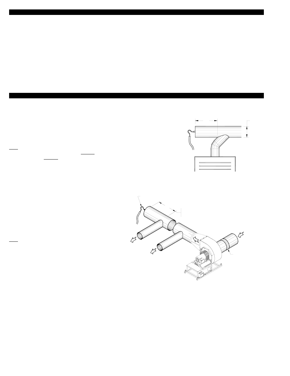
TRANSDUCER SENSING TUBE INSTALLATION
FOR MECHANICAL DRAFT INSTALLATIONS
The TD-2 Transducer sensing tube should be installed in
the cap of a tee or rear of a common manifold. The tee is
necessary so that only static pressure is measured. If the
transducer sensing tube is installed in the side of a vent
pipe it will also measure velocity pressure, giving an incor-
rect signal back to the CPC-3 Controller. If mounting on the
side of the pipe is unavoidable, the sensing tube should be
flush to the interior wall of the vent pipe. Typically, draft
applications should sample at a point in back of the vent
connection that is farthest from the inducer/blower, See
Diagram B.
FOR “SEALED” COMBUSTION AIR APPLICATIONS
The TD-2 Transducer sensing tube should be installed in
the capped end of a common supply manifold. This is nec-
essary so that only static pressure is measured. If the
transducer sensing tube is installed in the side of a duct it
will also measure velocity pressure, giving an incorrect sig-
nal back to the CPC-3 Controller. If mounting on the side of
the duct pipe is unavoidable, the sensing tube should be
flush to the interior wall of the duct. If a filter is installed it
must be positioned between the blower inlet and intake
opening, See Diagram C.
FOR “OPEN” COMBUSTION AIR APPLICATIONS
In "Open" mode the mechanical room air is sampled and an adjacent space is referenced. Referencing an adjacent space within the
building typically provides a more stable reference pressure than referencing outdoor air. In both cases, the goal is to reference static
pressure. Don't sample pressures at locations that can be affected by frequently opened doors, elevator shafts, ventilation fans and
diffusers. The model IPS-1 includes a decorative cover, sampling tube and fittings and when used in conjunction with the TD-3
Transducer may be used to sample indoor reference pressure. It reduces the effects of air movement on the sampling tube and pro-
vides a finished look. Varying wind speeds will affect outdoor reference pressure and are difficult to neutralize. If sampling outdoor ref-
erence pressure, the model WW-1 may be used in conjunction with the TD-3 Transducer to help neutralize the effects of winds. For
best performance mount the WW-1 at least one foot away from an outside wall
3
D
2D
FROM VENTER
HEATER FURTHEST
8054004 12/8/04
BACK FROM THE MANIFOLD.
BE 2 TIMES THE DIAMETER OF THE PIPE
IF POSSIBLE, THE SENSING TUBE SHOULD
BACK FROM THE LAST HEATER MANIFOLD.
BE 2 TIMES THE DIAMETER OF THE PIPE
IF POSSIBLE, THE SENSING TUBE SHOULD
2D
FIGURE 8054005 12/9/04
LAST
HEAT
ER
FIRST
HEAT
ER
COM
BUSTION AIR
MA
NIFO
LD
COMBUSTION
AIR INTAKE
INSTALLER-SUPPLIED
FILTRATION MUST BE ON
BLOWER INLET SIDE.
SENSING TUBE
DIAGRAM B
DIAGRAM C