Tjernlund CPC-3 Constant Pressure Controller Startup Manual 8504125 User Manual
Page 10
9
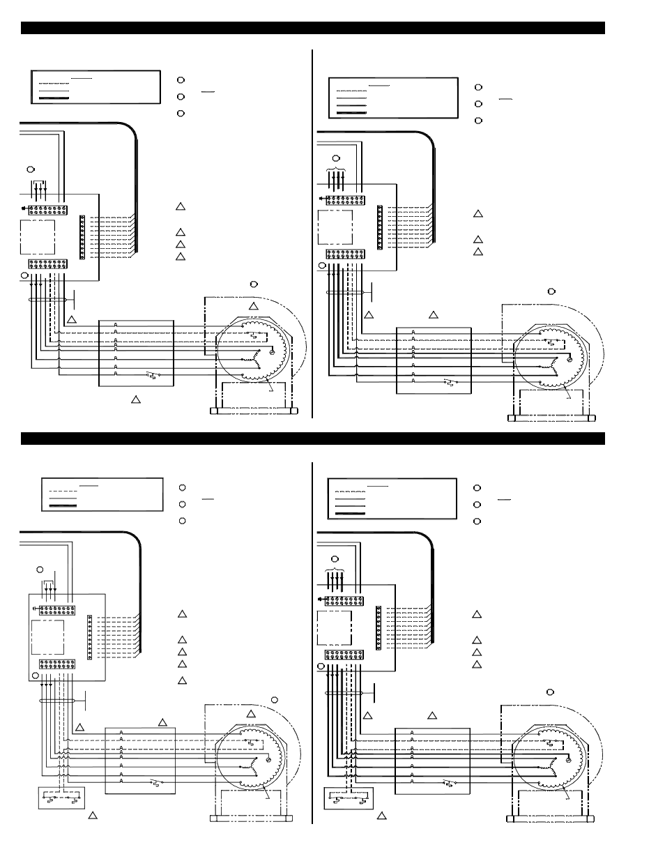
VSUB INDUCER OR COMBUSTION AIR BLOWER INTERLOCK WITH VFD
VSUB DRAFT INDUCER INTERLOCK WITH VFD
230 VOLT VSUB DRAFT INDUCER WIRING
460 VOLT VSUB DRAFT INDUCER WIRING
RED
ORANGE
BLUE
GREEN
BLACK
BLACK
BLACK
VSUB BLOWER
TSTAT
MOTOR HEATER
GROUND
MOTOR LIMIT
MOTOR
Max. length:
dedicated metal conduit.
Wiring is to be in
230 VAC SUPPLY / LOAD WIRING
LEGEND:
LOW VOLTAGE / DC CONTROL WIRING
300' (91m) @ 230 VAC
TJERNLUND DRIVE MODEL
VFD- _ _ _ _ _ _ _ 2C3
"2" means "230 VAC"
VFD
CONTROL
BOX
M1
M2
M3
MG
ND
S1
S2
F1
F2
GN
D
L1
L2/
N
L3
NC
NC
L
L
MB
MC
M1
M2
S1
S2
SC
S3
D-
D+
plate rating before applying power. Improper supply voltage
Verify that the input power voltage matches the VFD's name-
All wiring must be in metal conduit (best) or shielded cable.
the same conduit. Undesired VFD operation could result.
Do not run the VFD's input power and output power wiring in
Verify that the blower (VSUB 8/12/16/20) is wired for the
output voltage from the VFD. If not correct, severe damage to
3.
2.
1.
3.
2.
WARNINGS:
CAUTIONS:
1.
to the VFD could damage the VFD.
the blower and/or the VFD could result.
When the system is completely installed, perform the safety
interlock and operational test as outlined in the installation
4.
manuals. Failure to do these tests could result in an unsafe
and/or incorrectly operating system.
"C" means "Closed Loop"
"3" means "CPC-3 Control"
3
3
BLACK
VIOLET
ORANGE
GRN/YEL
BLUE
YELLOW
WHT/RED
RED
GRAY
WHT/BRN
VFD COMMUNICATIONS CABLE
& 30 WATTS FOR VSUB20)
ARCTIC-DUTY
MOTOR HEATER
(15 WATTS FOR VSUB8,12,16
RED
WINDINGS
MOTOR
2
A
DD F
O
R 208-230 V
A
C 3Ø
208-230 V
A
C 1Ø /
60 HZ
4 x 4 WEATHERPROOF
BOX AND WHIP
2
This blower is shipped from the factory wired for 460 VAC.
4.
Reconfigure the motor wiring at the motor for 230 VAC.
See the Motor Label for details.
4
Route transducer wiring in metal conduit or use Belden Shield
Cable #9939 or equivalent. Make sure the transducer wiring
does not contain or cross line voltage wiring or undesired
Use caution to ensure that the wiring to the transducer is
Improper wiring to the transducer will destroy the transducer.
correct before activating the CPC-3 controller.
transducer performance may result.
INCLUDED CABLE
NOTES:
If the provided 10-foot, 10-wire VFD control cable is not long
1.
enough to meet the application needs, use caution to ensure
that the connections from the VFD to the CPC-3 controller
are correctly located. MB to MB, MC to MC, etc. In addition,
Use caulking to seal the electrical box cover to the electrical
2.
box, and to seal the conduit holes to hole plugs.
reference the Wire Length Table.
If required, non-fused disconnects are to be supplied by the
3.
installer.
3
FIGURE 8052019 11/18/04
460 VAC SUPPLY / LOAD WIRING
plate rating before applying power. Improper supply voltage
Verify that the input power voltage matches the VFD's name-
All wiring must be in metal conduit (best) or shielded cable.
the same conduit. Undesired VFD operation could result.
Do not run the VFD's input power and output power wiring in
Verify that the blower (VSUB 8/12/16/20) is wired for the
output voltage from the VFD. If not correct, severe damage to
3.
2.
1.
3.
2.
WARNINGS:
CAUTIONS:
1.
to the VFD could damage the VFD.
the blower and/or the VFD could result.
When the system is completely installed, perform the safety
interlock and operational test as outlined in the installation
4.
manuals. Failure to do these tests could result in an unsafe
and/or incorrectly operating system.
NOTES:
If the provided 10-foot, 10-wire VFD control cable is not long
1.
enough to meet the application needs, use caution to ensure
that the connections from the VFD to the CPC-3 controller
are correctly located. MB to MB, MC to MC, etc. In addition,
"C" means "Closed Loop"
"3" means "CPC-3 Control"
460 VAC / 3Ø / 60 HZ
3
RED
ORANGE
BLUE
GREEN
BLACK
BLACK
BLACK
VSUB BLOWER
TSTAT
MOTOR HEATER
GROUND
MOTOR LIMIT
4 x 4 WEATHERPROOF
BOX AND WHIP
MOTOR
Max. length:
dedicated metal conduit.
Wiring is to be in
230 VAC SUPPLY / LOAD WIRING
LEGEND:
LOW VOLTAGE / DC CONTROL WIRING
100' (30m) @ 460 VAC
TJERNLUND DRIVE MODEL
VFD- _ _ _ _ _ _ _ 4C3
"4" means "460 VAC"
2
VFD
CONTROL
BOX
M1
M2
M3
MG
ND
S1
S2
F1
F2
GN
D
L1
L2/
N
L3
NC
NC
L
L
MB
MC
M1
M2
S1
S2
SC
S3
D-
D+
3
BLACK
VIOLET
ORANGE
GRN/YEL
BLUE
YELLOW
WHT/RED
RED
GRAY
WHT/BRN
Use caulking to seal the electrical box cover to the electrical
2.
box, and to seal the conduit holes to hole plugs.
2
VFD COMMUNICATIONS CABLE
reference the Wire Length Table.
& 30 WATTS FOR VSUB20)
ARCTIC-DUTY
MOTOR HEATER
(15 WATTS FOR VSUB8,12,16
RED
WINDINGS
MOTOR
Route transducer wiring in metal conduit or use Belden Shield
Cable #9939 or equivalent. Make sure the transducer wiring
does not contain or cross line voltage wiring or undesired
Use caution to ensure that the wiring to the transducer is
Improper wiring to the transducer will destroy the transducer.
correct before activating the CPC-3 controller.
transducer performance may result.
INCLUDED CABLE
If required, non-fused disconnects are to be supplied by the
3.
installer.
3
FIGURE 8052018 11/18/04
230 VOLT VSUB COMBUSTION AIR BLOWER WIRING
460 VOLT VSUB COMBUSTION AIR BLOWER WIRING
plate rating before applying power. Improper supply voltage
Verify that the input power voltage matches the VFD's name-
All wiring must be in metal conduit (best) or shielded cable.
the same conduit. Undesired VFD operation could result.
Do not run the VFD's input power and output power wiring in
Verify that the blower (VSUB 8/12/16/20) is wired for the
output voltage from the VFD. If not correct, severe damage to
3.
2.
1.
3.
2.
WARNINGS:
CAUTIONS:
1.
to the VFD could damage the VFD.
the blower and/or the VFD could result.
When the system is completely installed, perform the safety
interlock and operational test as outlined in the installation
4.
manuals. Failure to do these tests could result in an unsafe
and/or incorrectly operating system.
NOTES:
If the provided 10-foot, 10-wire VFD control cable is not long
1.
enough to meet the application needs, use caution to ensure
that the connections from the VFD to the CPC-3 controller
are correctly located. MB to MB, MC to MC, etc. In addition,
"C" means "Closed Loop"
"3" means "CPC-3 Control"
3
3
BLACK
VIOLET
ORANGE
GRN/YEL
BLUE
YELLOW
WHT/RED
RED
GRAY
WHT/BRN
RED
ORANGE
BLUE
GREEN
BLACK
BLACK
BLACK
VSUB BLOWER
TSTAT
MOTOR HEATER
GROUND
MOTOR LIMIT
4 x 4 WEATHERPROOF
BOX AND WHIP
FFP-1
Max. length:
dedicated metal conduit.
Wiring is to be in
230 VAC SUPPLY / LOAD WIRING
LEGEND:
LOW VOLTAGE / DC CONTROL WIRING
300' (91m) @ 230 VAC
TJERNLUND DRIVE MODEL
VFD- _ _ _ _ _ _ _ 2C3
"2" means "230 VAC"
VFD
CONTROL
BOX
M1
M2
M3
MG
ND
S1
S2
F1
F2
GN
D
L1
L2/
N
L3
NC
NC
L
L
MB
MC
M1
M2
S1
S2
SC
S3
D-
D+
Use caulking to seal the electrical box cover to the electrical
2.
box, and to seal the conduit holes to hole plugs.
2
VFD COMMUNICATIONS CABLE
reference the Wire Length Table.
& 30 WATTS FOR VSUB20)
ARCTIC-DUTY
MOTOR HEATER
(15 WATTS FOR VSUB8,12,16
RED
WINDINGS
MOTOR
Route transducer wiring in metal conduit or use Belden Shield
Cable #9939 or equivalent. Make sure the transducer wiring
does not contain or cross line voltage wiring or undesired
Use caution to ensure that the wiring to the transducer is
Improper wiring to the transducer will destroy the transducer.
correct before activating the CPC-3 controller.
transducer performance may result.
The FFP-1 will disable the combustion air blower when
5.
excessively hot or cold room air is detected. Refer to the
FFP-1 installation instructions for details.
REFER TO FFP-1 INSTALLATION
INSTRUCTIONS FOR DETAILS
HEAT LIMIT
FREEZE LIMIT
5
This blower is shipped from the factory wired for 460 VAC.
4.
Reconfigure the motor wiring at the motor for 230 VAC.
See the Motor Label for details.
2
A
DD F
O
R
208-230 V
A
C
MOTOR
4
INCLUDED CABLE
3
FIGURE 8052021 11/18/04
8052021 S
H
E
E
T
2
If required, non-fused disconnects are to be supplied by the
3.
installer.
208-230 V
A
C 3Ш
1Ш /
60 HZ
460 VAC SUPPLY / LOAD WIRING
plate rating before applying power. Improper supply voltage
Verify that the input power voltage matches the VFD's name-
All wiring must be in metal conduit (best) or shielded cable.
the same conduit. Undesired VFD operation could result.
Do not run the VFD's input power and output power wiring in
Verify that the blower (VSUB 8/12/16/20) is wired for the
output voltage from the VFD. If not correct, severe damage to
3.
2.
1.
3.
2.
WARNINGS:
CAUTIONS:
1.
to the VFD could damage the VFD.
the blower and/or the VFD could result.
When the system is completely installed, perform the safety
interlock and operational test as outlined in the installation
4.
manuals. Failure to do these tests could result in an unsafe
and/or incorrectly operating system.
NOTES:
If the provided 10-foot, 10-wire VFD control cable is not long
1.
enough to meet the application needs, use caution to ensure
that the connections from the VFD to the CPC-3 controller
are correctly located. MB to MB, MC to MC, etc. In addition,
"C" means "Closed Loop"
"3" means "CPC-3 Control"
460 VAC / 3Ø / 60 HZ
3
230 VAC SUPPLY / LOAD WIRING
LEGEND:
LOW VOLTAGE / DC CONTROL WIRING
100' (30m) @ 460 VAC
TJERNLUND DRIVE MODEL
VFD- _ _ _ _ _ _ _ 4C3
"4" means "460 VAC"
2
VFD
CONTROL
BOX
M1
M2
M3
MG
ND
S1
S2
F1
F2
GN
D
L1
L2/
N
L3
NC
NC
L
L
MB
MC
M1
M2
S1
S2
SC
S3
D-
D+
3
BLACK
VIOLET
ORANGE
GRN/YEL
BLUE
YELLOW
WHT/RED
RED
GRAY
WHT/BRN
Use caulking to seal the electrical box cover to the electrical
2.
box, and to seal the conduit holes to hole plugs.
2
VFD COMMUNICATIONS CABLE
reference the Wire Length Table.
& 30 WATTS FOR VSUB20)
ARCTIC-DUTY
MOTOR HEATER
(15 WATTS FOR VSUB8,12,16
RED
WINDINGS
MOTOR
Route transducer wiring in metal conduit or use Belden Shield
Cable #9939 or equivalent. Make sure the transducer wiring
does not contain or cross line voltage wiring or undesired
Use caution to ensure that the wiring to the transducer is
Improper wiring to the transducer will destroy the transducer.
correct before activating the CPC-3 controller.
transducer performance may result.
The FFP-1 will disable the combustion air blower when
4.
excessively hot or cold room air is detected. Refer to the
FFP-1 installation instructions for details.
REFER TO FFP-1 INSTALLATION
INSTRUCTIONS FOR DETAILS
HEAT LIMIT
FREEZE LIMIT
4
MOTOR
INCLUDED CABLE
If required, non-fused disconnects are to be supplied by the
3.
installer.
3
FIGURE 8052020 11/18/04
RED
ORANGE
BLUE
GREEN
BLACK
BLACK
BLACK
VSUB BLOWER
TSTAT
MOTOR HEATER
GROUND
MOTOR LIMIT
4 x 4 WEATHERPROOF
BOX AND WHIP
FFP-1
Max. length:
dedicated metal conduit.
Wiring is to be in