Tjernlund CPC-3 Constant Pressure Controller Startup Manual 8504125 User Manual
Page 5
CPC-3 KEYPAD LAYOUT
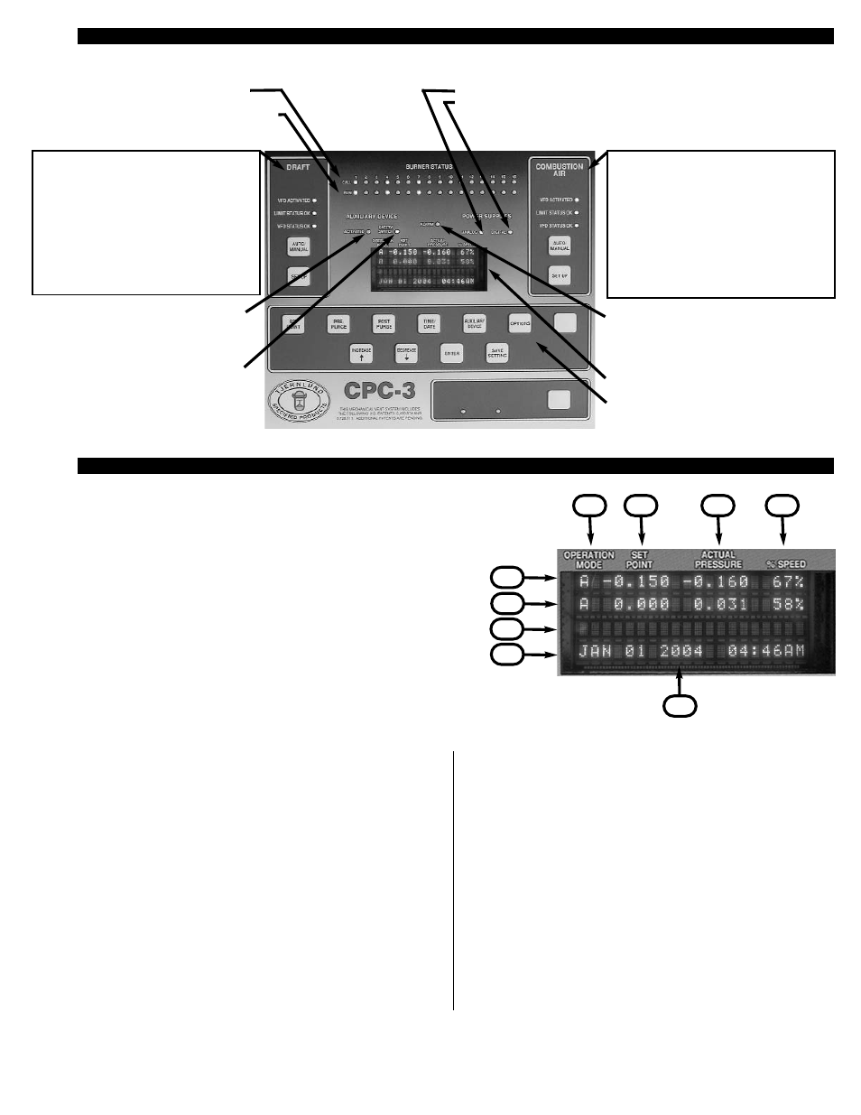
CPC-3 DISPLAY
4
AUXILIARY DEVICE Green ACTIVATED LED
indicates AUX. CONTROL Relay contacts (C & O)
are closed to actuate auxiliary devices such as a
motorized louver.
AUXILIARY DEVICE Green SAFETY SWITCH
LED indicates Auxiliary device safety contacts
such as a damper end switch are in a closed
position within 90 seconds after a call for heat.
Red ALARM LED indicates a system fault is
detected. On board audible alarm buzzer can be
activated. Alarm relay contacts (NO, C & NC) can
be interlocked with building management system
or other device.
CPC-3 Display window
Additional Programming Keys
BURNER STATUS
Amber CALL LED indicates burner call for heat
Green RUN LED indicates burner approved to fire
after completing CPC-3 safety circuit
POWER SUPPLIES
ANALOG - 24 VDC CPC-3 on board power supply for check circuits and transducer
DIGITAL - 5 VDC CPC-3 on board power supply for CPC-3 microcontroller and logic
COMBUSTION AIR Setup portion of CPC-3
VFD ACTIVATED - Green LED shows VFD turned
on by CPC-3
LIMIT STATUS OK -Green LED shows all limits /
safeties closed (i.e. motor or freeze limits)
VFD STATUS OK -Green LED shows VFD is not
faulted, no LED indicates VFD fault
Auto / Manual mode and Setup for Combustion Air
Options
DRAFT Setup portion of CPC-3
VFD ACTIVATED- Green LED shows VFD turned
on by CPC-3
LIMIT STATUS OK - Green LED shows all limits /
safeties closed (i.e. motor limit, heat limits, tilt
switches)
VFD STATUS OK - Green LED shows VFD is not
faulted, no LED indicates VFD fault
Auto / Manual mode and Setup for Draft Options
A
B
C
D
E
F
G
H
I
A. The 1st display line is for the Draft System. If the Draft System is
not active, the top line will read "INDUCER INACTIVE" and will
not display an operation mode, set point, actual pressure or
motor operating speed %.
B. The 2nd display line is for the Combustion Air System. If
the Combustion Air System is not active, the second line will read
"COMBUS. AIR INACTIVE" and will not display an operation
mode, set point, actual pressure or motor operating speed %.
C. The 3rd display line is the "Message" line for different operating
phases such as, Start Up, Pre-Purge, Post Purge, Etc. This line
also displays faults that have been detected within the overall
operation of the control. A fault message displayed will be
specific to the fault type, the draft or combustion air system and
which operation phase the control was in when the fault occur-
red. If the key pad is unlocked, this line converts to a progamma-
ble menu line where options are displayed.
D. The 4th and last display line is for the Date and Time. Used
when the keypad is unlocked, as a programmable menu options
line. In short, when the keypad is unlocked, the bottom 2 lines
become menu information lines for the key functions and their
options.
E. The 1st column of the display is for the OPERATION MODE and
will display an "A" if the Draft or Combustion Air System is active
in “Automatic” mode or an "M" if in “Manual” mode.
F. The 2nd column of the display is for the SET POINT of the
Draft or Combustion Air system set by the installer. The pressure
units displayed (Inches of water column or Pascals) are set
under the "Options" key. The factory default set point is
-0.15" WC. for Draft and 0.00" WC. for Combustion Air.
G. The 3rd column of the display is for the ACTUAL PRESSURE of
the Draft or Combustion Air System, updated every second based
on the pressure sensed by the pressure transducer. If the Draft
or Combustion Air System is Active, the Actual Pressure will be
displayed 100% of the time. As with the set point, the units of
pressure measurement will change based on Inches of WC or
Pascals in "Options".
H. The 4th and last column of the display is for the %SPEED of the
Draft or Combustion Air System. This speed percentage is direct
ly rendered from the control voltage signal that is being provided
by the CPC-3 controller to the VFD. The scale is 1 VDC to 10 VDC.
1 VDC = 1% motor speed, 10 VDC = 100% motor speed. Any-
time the control is telling the motor to run, the percentage speed
is illustrated here.
I. Date and Time display when not used for programming options.