Cpc-3 control – Tjernlund CPC-3 Constant Pressure Controller Startup Manual 8504125 User Manual
Page 7
6
Positions P1 & P2 are for the PSA-1, manual mode proving switch. Position P1 outputs a 5 VDC signal to the PSA-1 Proving
Switch. When the switch closes it returns the signal to position P2, allowing interlocked heaters to operate with the CPC-3 in
Manual Mode.
Positions G, R & B connect to a TD-Series transducer. Position G receives the 1-10 VDC output from the transducer. Position R is
the 24 VDC power supply to the transducer. Position B is the ground for the transducer.
Positions D+ & D- connect to the VFD through the included communications cable. Position D+ outputs a 1-10 VDC signal to the
VFD to modulate the inducer/blower. Position D- is the reference ground.
Positions S3, SC, S2 and S1 connect to the VFD through the included communications cable. These connections enable reset of
a faulted VFD and reverse the rotation of an inducer/blower from the CPC-3 controller.
Positions M1, M2, MC and MB connect to the VFD through the included communications cable. Position M1 outputs a 5 VDC sig-
nal to the inducer/blower limit circuits. This signal must return to position M2 or a mechanical fault will be posted on the display
and the Limit Status OK LED will not be lit. Position MC outputs a 5 VDC signal to a N/C fault relay within the VFD. This signal
must return to position MB or a VFD fault will be noted in the display and the VFD Status OK Green LED will not be lit.
G1 & H1) Inducer / C.A. Blower Rotation Selectors:
Below the Inducer (Draft) and Combustion Air terminal strips are two sets of dip switches. These dip switches determine the
rotation of the inducer/blower being controlled by that particular terminal strip. The two dip switches at each position must
always be switched opposite of each other or the VFD will receive simultaneous FWD/REV run commands, causing it to
fault. See "Checking Rotation", page 12.
I) CPC-3 Reset Button:
Pressing this button resets the CPC-3 controller with a "soft boot". It can be used in lieu of the power switch to "re-boot" the micro-
controllers of the CPC-3 without power spiking the board.
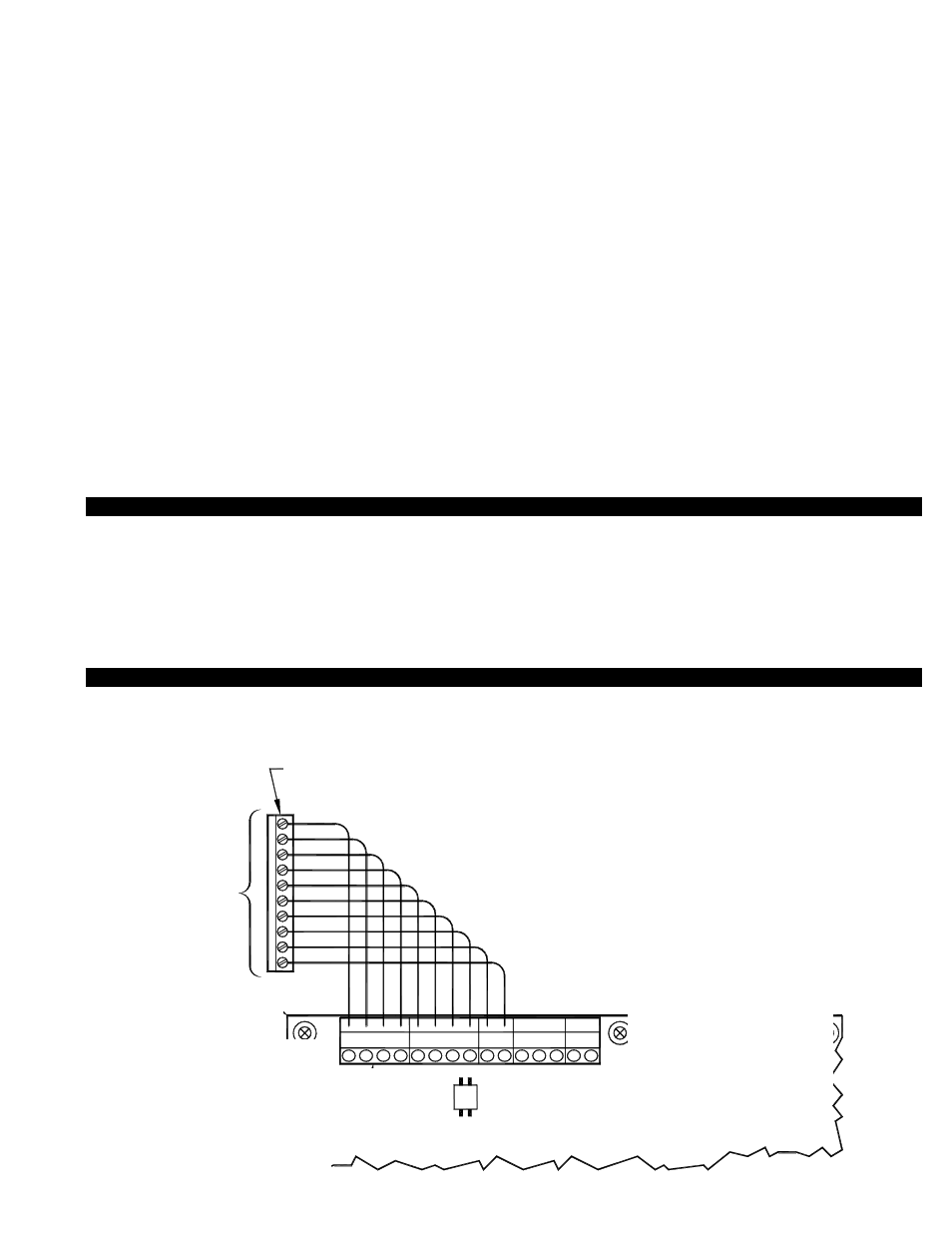
LOW VOLTAGE VFD CONTROL CABLE WIRING TO CPC-3
FIGURE 8055010 8/30/04
D+
D-
S3S
CS2
S1M2
M1MC
MB
B
R
G
B
R
G
S1S2
CPC-3 CONTROL
SENSORS
AUX. SENSO
R
INDUCE
R
2
1
B
R
G
P1
P2
SELECTOR
INDUCER
MOTOR
ROTATION
from the Inducer VFD to the CPC-3 Inducer terminal strip.
Be sure to route the communications cable in metal conduit
1.
NOTES:
to route each wire from the Inducer VFD to the CPC-3
If a longer communication cable is required, make sure
2.
Inducer terminal strip correctly. MB to MB, MC to MC, etc.
BLACK
VIOLET
ORANGE
GRN/YEL
BLUE
YELLOW
WHT/RED
RED
WHT/BRN
GRAY
WITH VFD
10 FOOT
COMMUNICATION
CABLE PROVIDED
NOT USED -
FOR FUTURE
DEVELOPMENT
NOT USED -
FOR FUTURE DEVELOPMENT
THE INDUCER
TERMINAL STRIP
INSERT PLUG INTO THE INDUCER
VFD RECEPTACLE
GRAY
WH
T
/B
R
N
RED
WH
T
/R
E
D
YELLO
W
GRN/YEL
BLUE
ORANGE
VIOL
ET
BLACK
TOP LEFT CORNER
CPC-3 CONTROL
BOARD
RS232
COM.
PORT
NOTE: The diagram below is suitable for both the Inducer or Combustion Air side of the the CPC-3 board. While the software that
runs draft or combustion air differs, the communication to the VFD's that control the Inducer / C.A. Blower is identical. The following
information is applicable to both the CPC-3 Inducer and Combustion Air terminal strips.
WIRING
All wiring from the Inducer / C.A. Blower to the heater must be in compliance with the local codes or in their absence, the National
Electric Code (NFPA 70).
All wiring from the Inducer/blower to the heater must be appropriate class 1 wiring installed in rigid metal conduit or intermediate metal
conduit. This installation manual does not contain any system design documentation. Installation and use of Tjernlund controls like the
EXP-4E Heater Interlock Expansion boards or VFD-Series Variable Frequency Drives are not covered by this manual. Please refer to
those installation manuals for details.
INDUCER OR
COMBUSTION AIR
MOTOR ROTATION
SELECTOR
NOTES:
1. Be sure to route the communications cable in metal conduit
from the Inducer or C. A. Blower to the respective CPC-3
Inducer or Combustion Air terminal strip.
2. If a longer communication cable is required, make sure to route
each wire from the Inducer or C.A. Blower VFD to the respec-
tive CPC-3 Inducer or Combustion Air terminal strip.