D1 a b i c1 e f h1 g1 h g – Tjernlund CPC-3 Constant Pressure Controller Startup Manual 8504125 User Manual
Page 6
5
MB
MC
M1
M2
S1
S2
SC
S3
D-
D+
B
R
G
P1
P2
S2
S1
S2
S1
P2P1
G
R
B
D+
D-
S3
SC
S2
S1
M2
M1
MC
MB
B
R
G
B
R
G
S1S2
O
CS
2
S
1
12
12
NC
C
NO
N
L
L N
L N
L N
A B
A B
A B
A B
2
1
3
4
4
3
1
2
4
3
1
2
4
3
1
2
POWER TERMINAL
MAIN AC
EXP-4E
POWER TERMINALS
HEATER 1
HEATER 2
HEATER 3
HEATER 4
INDUCER PORT
COMBUSTION AIR PORT
BOARD
ALARM
POWER
DIGITAL
ANALOG AND
SUPPLIES
KEYPAD
CONNECTORS
CALL
RETURN
JUMPERS
PORT
DEVICE
AUXILIARY
PORT
ALARM
REMOTE
PORTS
SIGNAL
EXP-4E
MICROCONTROLLERS
SWITCH
RESET
SELECTOR
INDUCER
MOTOR
ROTATION
ROTATION
MOTOR
COMBUSTION AIR
SELECTOR
CONTROLLER DISPLAY
DRY1
A24V
A115V
D
C
B115V
B24V
DRY2
C115V
C24V
DRY3
D115V
D24V
DRY4
D1
D1
D1
D1
A B
I
C1
E
F
H1
G1
H
G
FUTURE USE
FUTURE USE
FUTURE
USE
USE
FUTURE
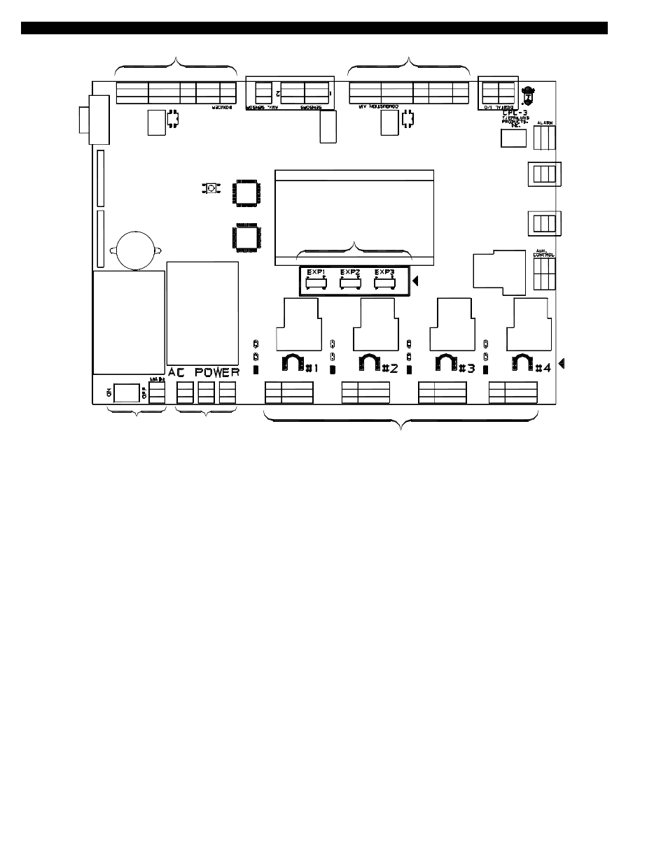
FIGURE 8081005
CPC-3 BOARD CALLOUTS
A) CPC-3 Main Power Switch
B) Power Supply Input Terminals: Accepts either 115 or 230 VAC, 50/60 Hz. 230V power can be suppied from VFD L & L Terminals.
C) Power Supply Output Terminals: Supply power to accessory EXP-4E Expansion boards.
C1) EXP-4E Expansion Modules: Communications connections from EXP-4E Expansion boards.
D) Heater Interlock Terminal Blocks (Four):
Positions A & B are for dry contact actuation, with A outputting 5 VDC and B needing 5 VDC to activate the CPC-3. Positions 1 &
2 require either 24 or 115 VAC from a heater control circuit to activate the CPC-3. A factory installed call return jumper wire above
each terminal block routes the voltage connected from position 1 to position 3. When the CPC-3 safety circuit is made it switches
position 3 to position 4, where the intercepted heater control circuit is routed back to the heater. Positions 3 & 4 are used indepen-
dent of positions 1 & 2. If the A & B dry contacts are used to activate the CPC-3 (Call return jumper wire must be removed).
D1) IMPORTANT: Each six position terminal block includes a RED jumper tab to select the heater interlock voltage that is
connected heater terminal block. Place RED jumper tab in Dry for positions A & B, 24V or 115V for positions 1 & 2 depening
upon heater interlock voltage)
E) Auxiliary Device Terminals:
Used to activate a motorized damper/louver in series with the inducer/blower activation by switching power to device through ter-
minal C & O. Position S1 outputs 5 VDC to be switched through a damper end switch and returned to position S2. This incorpor-
ates the end switch closure into the overall CPC-3 safety circuit. Positions S1 & S2 may also be used to react to the contact clos-
ure of a carbon monoxide alarm. The functions of C & O and S1 & S2 are independently activated through the Auxiliary Device key.
F) Remote Alarm Terminals:
Used to activate a remote alarm through either normally open or normally closed contacts. A power source is routed to the C posi-
tion and returned out of either the N/C or N/O positions if an alarm condition exists.
G & H) Draft and Combustion Air Terminals:
The CPC-3 can independently control mechanical draft and combustion air inducers/blowers. While the software that runs
these functions differs, the communications to the VFD's that control the inducer/blower is identical. The following information
is applicable to both the Inducer and Combustion Air terminal strips.