Carrier AQUAZONE 50PSW036-360 User Manual
Page 5
5
8. Remove any access panel screws that may be difficult to
remove once unit is installed.
Step 3 — Locate Unit —
The following guidelines
should be considered when choosing a location for the WSHP:
• Units are for indoor use only.
• Provide sufficient space for water and electrical
connections.
• Locate unit in an area that allows for easy access and
removal of access panels.
• Allow enough space for service personnel to perform
maintenance.
Step 4 — Mount Unit —
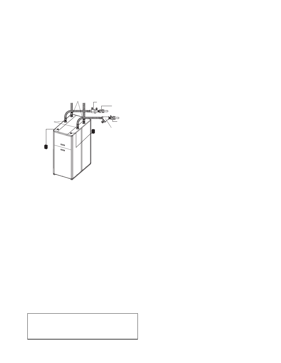
Mount unit as shown in Fig. 3.
Rod attachments must be able to support the weight of the unit.
See Table 1 for unit operating weight.
Step 5 — Connect Piping —
Depending on the appli-
cation, there are 3 types of WSHP piping systems to choose
from: water loop, ground-water and ground loop. Refer to the
Carrier System Design Manual for additional information.
All WSHP units utilize low temperature soldered female
pipe thread fittings for water connections to prevent annealing
and out-of-round leak problems which are typically associated
with high temperature brazed connections. When making pip-
ing connections, consider the following:
• A backup wrench must be used when making screw con-
nections to unit to prevent internal damage to piping.
• Insulation may be required on piping to avoid condensa-
tion in the case where fluid in loop piping operates at
temperatures below dew point of adjacent air.
• Piping systems that contain steel pipes or fittings may
be subject to galvanic corrosion. Dielectric fittings may
be used to isolate the steel parts of the system to avoid
galvanic corrosion.
• Units may be manifolded together via top water connects
to get increased temperatures, when piped in series, or
greater capacity, when piped in parallel.
WATER SUPPLY AND QUALITY — Check water supply.
Water supply should be plentiful and of good quality. See
Table 2 for water quality guidelines.
In all applications, the quality of the water circulated
through the heat exchanger must fall within the ranges listed in
the Water Quality Guidelines table. Consult a local water treat-
ment firm, independent testing facility, or local water authority
for specific recommendations to maintain water quality within
the published limits.
WATER LOOP APPLICATIONS — Water loop applica-
tions usually include a number of units plumbed to a common
piping system. Maintenance to any of these units can introduce
air into the piping system. Therefore, air elimination
equipment comprises a major portion of the mechanical room
plumbing.
The flow rate is usually set between 2.9 L/m and 3.9 L/m
per kW of cooling capacity. For proper maintenance and ser-
vicing, pressure-temperature (P/T) ports are necessary for tem-
perature and flow verification.
In addition to complying with any applicable codes, consid-
er the following for system piping:
• Piping systems utilizing water temperatures below
10.0 C require 13 mm closed cell insulation on all piping
surfaces to eliminate condensation.
• All plastic to metal threaded fittings should be avoided
due to the potential to leak. Use a flange fitted substitute.
• Teflon* tape thread sealant is recommended to minimize
internal fouling of the heat exchanger.
• Use backup wrench. Do not overtighten connections.
• Route piping to avoid service access areas to unit.
• The piping system should be flushed prior to operation to
remove dirt and foreign materials from the system.
Cooling tower/boiler systems typially use a common loop
maintained between 16 and 32 C. The use of a closed circuit
evaporative cooling tower with a secondary heat exchanger be-
tween the tower and the water loop is recommended. If an open
type cooling tower is used continuously, chemical treatment
and filtering will be necessary.
GROUND-WATER APPLICATIONS — In addition to
complying with any applicable codes, consider the following
for system piping:
• Install shut-off valves for servicing.
• Install pressure-temperature plugs to measure flow and
temperature.
• Boiler drains and other valves should be connected using
a “T” connector to allow acid flushing for the heat
exchanger.
• Do not overtighten connections.
• Route piping to avoid service access areas to unit.
• Use PVC SCH80 or copper piping material.
NOTE: PVC SCH40 should not be used due to system high
pressure and temperature extremes.
GROUND-LOOP APPLICATIONS — Temperatures be-
tween –3.9 and 43.3 C and a cooling capacity of 2.9 L/m and
3.9 L/m per kW are recommended. In addition to complying
with any applicable codes, consider the following for system
piping:
• Piping materials should be limited to only polyethylene
fusion in the buried sections of the loop.
• Galvanized or steel fittings should not be used at any
time due to corrosion.
• All plastic to metal threaded fittings should be avoided
due to the potential to leak. Use a flange fitted substitute.
• Do not overtighten connections.
• Route piping to avoid service access areas to unit.
• Pressure-temperature (P/T) plugs should be used to mea-
sure flow of pressure drop.
IMPORTANT: Failure to comply with the above required
water quality and quantity limitations and the closed-
system application design requirements may cause damage
to the tube-in-tube heat exchanger that is not the responsi-
bility of the manufacturer.
Fig. 3 — Typical Water Loop System —
Boiler, Tower, or Ground (Sizes 180,360 Shown)
Control
Wiring
Power
Disconnect
Source Connections
(Boiler/Tower/Ground)
Load Connections (Hot
Water/Chilled Water)
Automatic Flow
Regulator
Ball Valve
with Pressure
Temperature Port
Ball Valve
with Pressure
Temperature Port
Y Strainer with
Blow Down Valve
a50-8138
*Teflon is a trademark of E. I. du Pont de Nemours and Company.