Checking system charge, Refrigerant charging, Troubleshooting – Carrier AQUAZONE 50PSW036-360 User Manual
Page 19: Thermistor, Control sensors, Warning
19
but take care to prevent liquid from being carried over by the
gases.
Warm solution acts faster, but cold solution is just as effec-
tive if applied for a longer period.
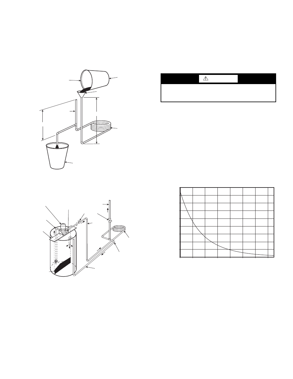
GRAVITY FLOW METHOD — Do not add solution faster
than vent can exhaust the generated gases.
When condenser is full, allow solution to remain overnight,
then drain condenser and flush with clean water. Follow acid
manufacturer’s instructions. See Fig. 12.
FORCED CIRCULATION METHOD — Fully open vent
pipe when filling condenser. The vent may be closed when
condenser is full and pump is operating. See Fig. 13.
Regulate flow to condenser with a supply line valve. If
pump is a nonoverloading type, the valve may be fully closed
while pump is running.
For average scale deposit, allow solution to remain in con-
denser overnight. For heavy scale deposit, allow 24 hours.
Drain condenser and flush with clean water. Follow acid manu-
facturer’s instructions.
Checking System Charge —
Units are shipped with
full operating charge. If recharging is necessary:
1. Insert thermometer bulb in insulating rubber sleeve on
liquid line near filter drier. Use a digital thermometer for
all temperature measurements. DO NOT use a mercury
or dial-type thermometer.
2. Connect pressure gage to discharge line near compressor.
3. After unit conditions have stabilized, read head pressure
on discharge line gage.
NOTE: Operate unit a minimum of 15 minutes before
checking charge. From standard field-supplied Pressure-
Temperature chart for R-410A, find equivalent saturated
condensing temperature.
4. Read liquid line temperature on thermometer; then
subtract from saturated condensing temperature. The dif-
ference equals subcooling temperature.
Refrigerant Charging
NOTE: Do not vent or depressurize unit refrigerant to atmo-
sphere. Remove and recover refrigerant following accepted
practices.
TROUBLESHOOTING
When troubleshooting problems with a WSHP, refer to
Table 13.
Thermistor —
A thermistor may be required for single-
phase units where starting the unit is a problem due to low
voltage. See Fig. 14 for thermistor nominal resistance.
Control Sensors —
The control system employs 2 nom-
inal 10,000 ohm thermistors (FP1 and FP2) that are used for
freeze protection. Be sure FP1 is located in the discharge fluid
and FP2 is located in the air discharge. See Fig. 15.
Fig. 12 — Gravity Flow Method
FILL CONDENSER WITH
CLEANING SOLUTION. DO
NOT ADD SOLUTION
MORE RAPIDLY THAN
VENT CAN EXHAUST
GASES CAUSED BY
CHEMICAL ACTION.
PAIL
FUNNEL
CONDENSER
PAIL
1.0 TO 1.2 m
VENT
PIPE
1.5 m APPROX
1-IN.
(25 mm)
PIPE
Fig. 13 — Forced Circulation Method
SUCTION
PUMP
SUPPORT
TANK
FINE MESH
SCREEN
RETURN
GAS VENT
PUMP
PRIMING
CONN.
GLOBE
VALVES
SUPPLY
1-IN.
(25 mm)
PIPE
CONDENSER
REMOVE WATER
REGULATING VALVE
WARNING
To prevent personal injury, wear safety glasses and gloves
when handling refrigerant. Do not overcharge system —
this can cause compressor flooding.
0.0
10.0
20.0
30.0
40.0
50.0
60.0
70.0
80.0
90.0
-17.7
-6.6
4.4
15.6
26.7
37.8
48.9
60.0
Temperature (C)
Re
s
is
ta
nce (kOhm)
Fig. 14 — Thermistor Nominal Resistance