Step 7 — wire low voltage connections, Pre-start-up system checkout – Carrier AQUAZONE 50PSW036-360 User Manual
Page 12
12
EXTERNAL LOOP POWER CONNECTION — If the unit
is to be connected to an external loop pump or flow controller,
connect the pump to the loop pump terminal block PB1. The
maximum power handling is 4 amps at 240-v. The pumps will
automatically cycle as required by the unit.
220-V
OPERATION
—
All 220/240-v units are factory
wired for 220-v. The transformers may be switched to 240-v
operation (as illustrated on the wiring diagram) by switching
the red (220-v) wire with the orange (240-v) wire at the L2
terminal.
380-VOLT OPERATION — All 380/415 volt units are factory
wired for 420 volts. The transformers may be switched to
380-volt operation by switching the brown (380 volt) wire
with the violet (420 volt) wire at the L1 terminal.
Step 7 — Wire Low Voltage Connections
THERMOSTAT CONNECTIONS
The thermostat should be wired directly to the Aquazone™
control board. See Fig. 4-7.
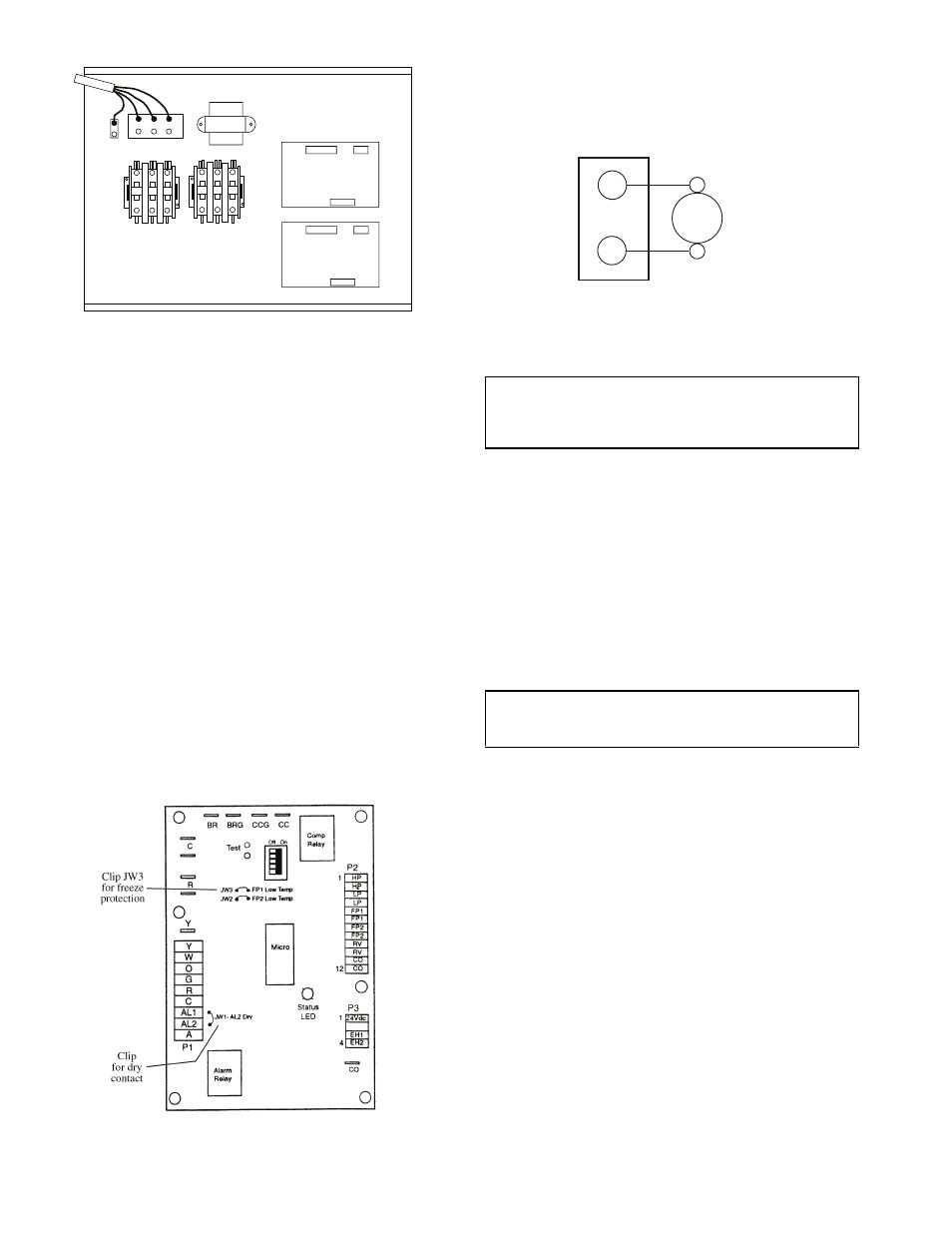
WATER FREEZE PROTECTION — The Aquazone control
allows the field selection of source fluid freeze protection
points through jumpers. The factory setting of jumper JW3
(FP1) is set for water at –1.1 C. In earth loop applications,
jumper JW3 should be clipped to change the setting to –12.2 C
when using antifreeze in colder earth loop applications. See
Fig. 9.
ACCESSORY CONNECTIONS — The terminal labeled A
on the control is provided to control accessory devices such as
water valves, electronic air cleaners, humidifiers, etc. This sig-
nal operates with the compressor terminal. See Fig. 10. Refer
to the specific unit wiring schematic for details.
NOTE: The A terminal should only be used with 24-v signals,
not line voltage signals.
WATER SOLENOID VALVES — Water solenoid valves
may be used on variable flow systems and ground water instal-
lations. A typical well water control valve wiring which can
limit waste water in a lockout condition is shown in Fig. 10. A
slow closing valve may be required to prevent water hammer.
When using a slow closing valve, special wiring conditions
need to be considered. The valve takes approximately 60 sec-
onds to open (very little water will flow before 45 seconds) and
it activates the compressor only after the valve is completely
opened by closing its end switch. When wired as shown, the
valve will have the following operating characteristics:
1. Remain open during a lockout.
2. Draw approximately 25 to 35-va through the “Y” signal
of the thermostat.
PRE-START-UP
System Checkout —
When the installation is complete,
follow the system checkout procedure outlined below before
starting up the system. Be sure:
1. Voltage is within the utilization range specifications of the
unit compressor and fan motor, and voltage is balanced
for 3-phase units.
2. Fuses, breakers and wire are correct size.
3. Low voltage wiring is complete.
4. Piping and system flushing is complete.
5. Air is purged from closed loop system.
6. System is balanced as required. Monitor if necessary.
7. Isolation valves are open.
8. Water control valves or loop pumps are wired.
9. Transformer switched to lower voltage tap if necessary.
10. Service/access panels are in place.
11. Control field-selected settings are correct.
Contactor -CC1
Transformer
C Control #1
Low V
oltage
Connector
Grnd
L2
L3
L1
Low V
oltage
Connector
Contactor -CC2
C Control #2
Power Distribution
Block
Fig. 8 — Typical Field Wiring
Fig. 9 — Typical Aquazone Control Board
Jumper Locations (Complete C Control Shown)
IMPORTANT: Two-compressor units with Complete C or
Deluxe D controls wired to terminal A will be turned off if
the controls are in lockout mode, even if the other board is
in normal operating mode.
IMPORTANT: This can overheat the anticipators of
electromechanical thermostats. Only use relay based
electronic thermostats.
Typical
Water
Valve
C
A
24 VAC
Terminal Strip
Fig. 10 — Typical Aquazone Accessory Wiring
(Deluxe D Control Shown)