0 load cell wiring, Load cell wiring, 16 otr truck scale assembly instructions – Rice Lake SURVIVOR OTR Steel Deck User Manual
Page 20: Cable to indicator, Pocket 4 conduit pocket 6 conduit, Pocket 4 conduit pocket 5 conduit, Module c
16
OTR Truck Scale Assembly Instructions
5.0
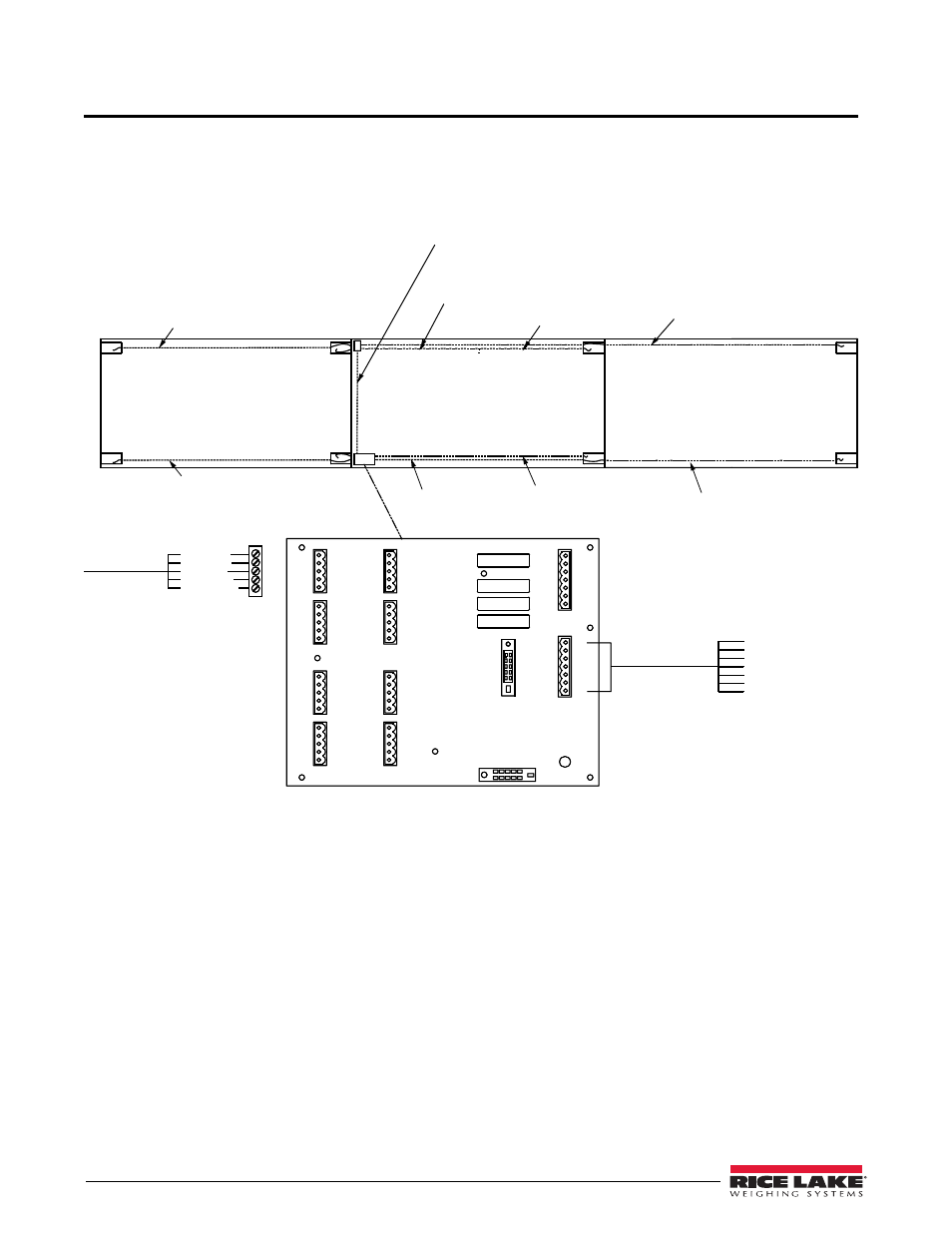
Load Cell Wiring
Electrical conduit is pre-installed at the factory and only needs to be connected between the modules and from the
modules to the junction box (J-box). Following conduit work, load cell cables are routed through each conduit from
the load cells to the J-box. All load cell cabling used for this installation comes in the shipping container. The
layout pattern for the electrical conduit on a three module truck scale installation is shown in Figure 5-1.
Figure 5-1. J-Box Wiring and Conduit Runs for a Four Section/Three Module Scale
Load Cell
Cable to
Connector
Pocket 1 Conduit
Pocket 8 Conduit
Pockets 1, 2, 3, 4
Conduit runs to J-Box
Pocket 5 Conduit
Module A
Module B
Pocket 3 Conduit
1
8
2
7
SI - Green
SI - White
EX - Red
EX - Black
SHD - Shield
+
-
+
-
+SI
-SI
+EX
-EX
SHD
+SI
-SI
+EX
-EX
SHD
+SI
-SI
+EX
-EX
SHD
+SI
-SI
+EX
-EX
SHD
J3
J4
J7
J8
J6
J5
J2
J1
+SI
-SI
+EX
-EX
SHD
+SI
-SI
+EX
-EX
SHD
+SI
-SI
+EX
-EX
SHD
+SI
-SI
+EX
-EX
SHD
Load Cell #1
Load Cell #3
Load Cell #8
Load Cell #6
Load Cell #2
Load Cell #4
Load Cell #7
Load Cell #5
+SI
-SI
+EX
-EX
SHD
-SEN
+SEN
SHD - Shield
+SI
-SI
+EX
-EX
SHD
-SEN
+SEN
Indicator/J10
Expansion/J9
Cable to Indicator
SI - Green
+
SI - White
-
EX - Red
+
EX - Black
-
SEN - Yellow
-
SEN - Blue
+
Pocket 4 Conduit
Pocket 6 Conduit
6
3
Pocket 4 Conduit
Pocket 5 Conduit
5
4
Module C