3 trimming paired sections – Rice Lake SURVIVOR ATV User Manual
Page 17
1
4
3
2
8
5
6
7
Trimming and Calibration
11
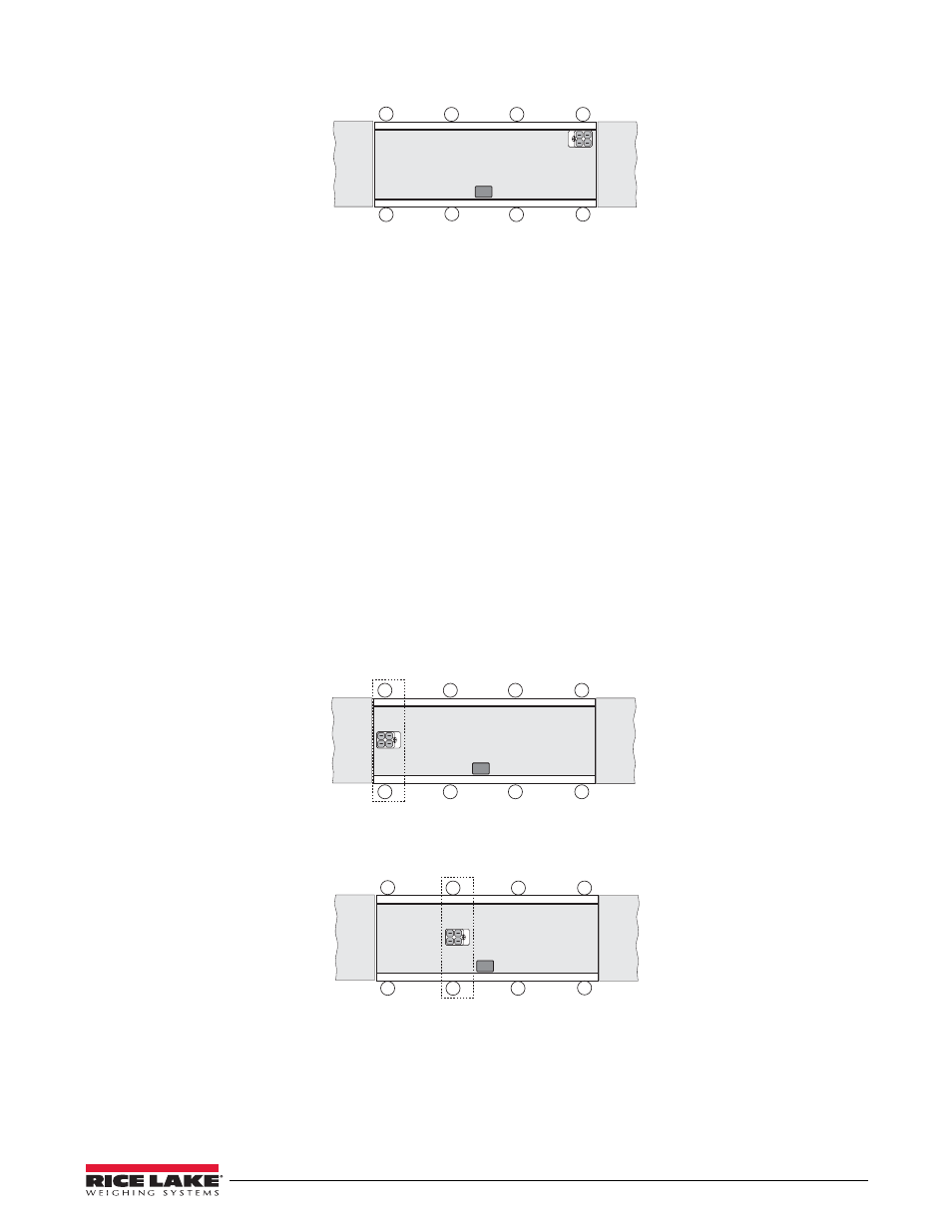
Figure 4-3. Trimming Load Cell Numbers 2, 3, and 4
3. The lowest reading of the four is the reference cell. Do not change that cell’s signal. Instead use the
individual cell potentiometers for the other three cells to reduce those signals to match your reference cell.
Remember that you turned all pots to full signal before starting, so you can not increase the signal from any
cell — only decrease signal by trimming with the pots.
4. Note that the best trim is always the least trim. If one of the four readings differs from the others by more
than 5% of the displayed counts, there is probably a mechanical problem with that load cell mount causing
the large difference. Find it and correct it before going on. Check for binding, an out-of-level or misaligned
link, or similar problems with the load cell and mount. Do not try to trim down large signal differences
with resistance pots — that only adds larger problems later because of interaction between mounts.
5. Park the loaded weight cart over one of the high-reading cells on side 1. Turn that cell’s individual
potentiometer until the displayed reading equals your recorded reference cell reading. Repeat for the other
two high-reading cells on side 1.
6. As adjustments are somewhat interactive, repeat the process in steps 1 – 5 until all four cells on side 1 read
within .1% of each other.
7. Repeat steps 1 – 6 for load cells 5 – 8 on side 2 of the scale.
4.3
Trimming Paired Sections
Now that all individual load cells are trimmed for equal output, pairs of load cells on opposite sides of the scale
must be trimmed for equal sectional output. This process is called section trimming.
1. Park the loaded weight cart in the middle of the scale and directly over an imaginary line connecting an
end pair of cells (1 and 8 in Figure 4-4). Record the indicator reading.
1
4
3
2
8
5
6
7
Figure 4-4. Trimming Paired Section 1:8
2. Move the weight cart directly over the next paired cell section (2, 7 in Figure 4-5) and record the indicator
reading. Do the same for the last two paired sections (cells 3, 6 and 4, 5)
.
1
4
3
2
8
5
6
7
Figure 4-5. Trimming Paired Sections 2:7, 3:6, and 4:5
3. Choose the lowest reading of the four as your reference section, which is not adjusted. Using the section
potentiometers, reload the other three sections in turn and trim the sections to match the reading of the
reference section. Recheck section readings a second time as the adjustment made can be somewhat
interactive.