2 j-box connections, J-box 2 detail, 8atv portable truck scale assembly instructions – Rice Lake SURVIVOR ATV User Manual
Page 12: Cable to j-box 2, Load cell cable to connector, Cable from j-box 1, Cable to indicator
8
ATV Portable Truck Scale Assembly Instructions
3.2
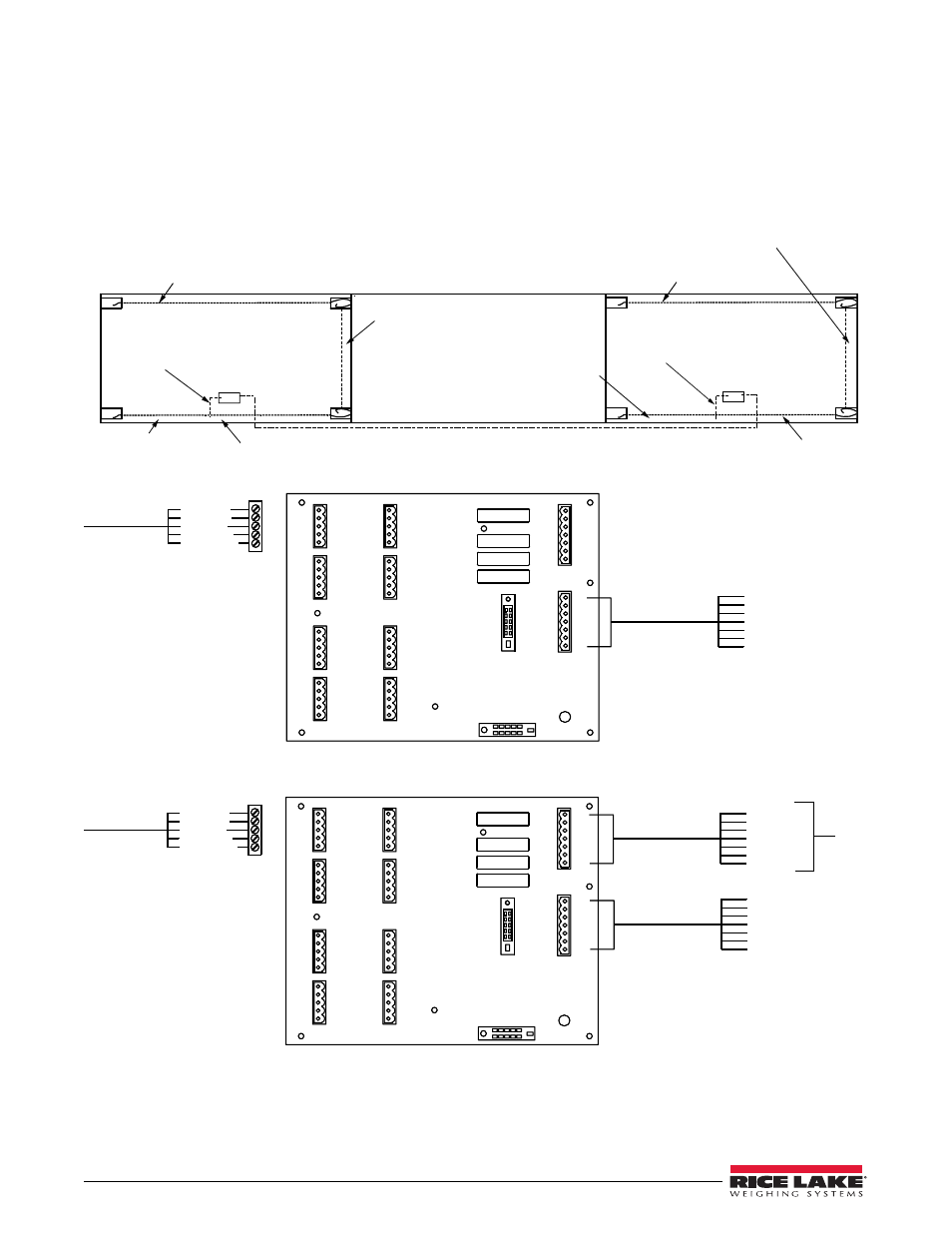
J-Box Connections
Each J-box contains a JB8SPT summing board with DC transient protection devices. A desiccant such as the
RLWS Industrial Corrosion Inhibitor (PN 16037) should be added to the J-box before final closure.
Each self-contained module has a single J-box located in the J-box pocket. A summing card mounted within the
J-box is used to make all cable terminal connections. All terminal pins are clearly marked as to function.
Load Cell
Cable to
Connector
Load Cell 1 Conduit
Module A
Module B
Load Cell 1, 2
and 3 Conduit
1
4
2
3
SI - Green
SI - White
EX - Red
EX - Black
SHD - Shield
+
-
+
-
+SI
-SI
+EX
-EX
SHD
+SI
-SI
+EX
-EX
SHD
+SI
-SI
+EX
-EX
SHD
+SI
-SI
+EX
-EX
SHD
J3
J4
J7
J8
J6
J5
J2
J1
+SI
-SI
+EX
-EX
SHD
+SI
-SI
+EX
-EX
SHD
+SI
-SI
+EX
-EX
SHD
+SI
-SI
+EX
-EX
SHD
Load Cell #1
Load Cell #3
Load Cell #8
Load Cell #6
Load Cell #2
Load Cell #4
Load Cell #7
Load Cell #5
+SI
-SI
+EX
-EX
SHD
-SEN
+SEN
SHD - Shield
+SI
-SI
+EX
-EX
SHD
-SEN
+SEN
Indicator/J10
Expansion/J9
Cable to J-Box 2
SI - Green
+
SI - White
-
EX - Red
+
EX - Black
-
SEN - Yellow
-
SEN - Blue
+
Load Cell
Cable to
Connector
SI - Green
SI - White
EX - Red
EX - Black
SHD - Shield
+
-
+
-
+SI
-SI
+EX
-EX
SHD
+SI
-SI
+EX
-EX
SHD
+SI
-SI
+EX
-EX
SHD
+SI
-SI
+EX
-EX
SHD
J3
J4
J7
J8
J6
J5
J2
J1
+SI
-SI
+EX
-EX
SHD
+SI
-SI
+EX
-EX
SHD
+SI
-SI
+EX
-EX
SHD
+SI
-SI
+EX
-EX
SHD
Load Cell #1
Load Cell #2
Load Cell #9
Load Cell #3
Load Cell #10
Load Cell #8
+SI
-SI
+EX
-EX
SHD
-SEN
+SEN
SHD - Shield
+SI
-SI
+EX
-EX
SHD
-SEN
+SEN
Indicator/J10
Expansion/J9
Cable from J-Box 1
SI - Green
+
SI - White
-
EX - Red
+
EX - Black
-
SEN - Yellow
-
SEN - Blue
+
SHD - Shield
Cable to Indicator
SI - Green
+
SI - White
-
EX - Red
+
EX - Black
-
SEN - Yellow
-
SEN - Blue
+
J-Box 2 Detail
1
4
2
3
Load Cell 1 and 2 Conduit
Load Cell
4 Conduit
Load Cell Cables
to J-Box
Load Cell 1 Conduit
Module A
Load Cell 1, 2
and 3 Conduit
Load Cell 1 and 2 Conduit
Load Cell
4 Conduit
Load Cell Cables
to J-Box
J-Box 2
J-Box 1
J-Box 1 Detail
Figure 3-2. J-Box Wiring and Conduit