3 calibrating the 920i – Rice Lake RailBoss Rail Scales - Installation Manual User Manual
Page 16
12
Railboss Railroad Track Scale
Use the following steps to properly trim the JB4SP junction box.
1. Make sure jumpers are in place to enable
trimming of the cells corresponding to each
load cell. See Figure 5-2 for the location of
jumpers JP1, JP2, JP3, and JP4.
2. Set all potentiometers fully clockwise to give
maximum signal output from each cell (see
Figure 5-2 for location of potentiometers)
3. Zero the indicator and place the RailBoss
Calibrator over each load cell in turn. The
amount of test weight is recommended to be
30,000 lb.
4. Record the value displayed on the indicator
after the calibrator is placed in turn on each
load cell. Allow the scale to return to zero each
time to check for friction or other mechanical
problems. Select the load cell which has the
lowest value as your reference point. This cell
will not be trimmed.
5. Replace the same test load over each cell in
turn. Using the corresponding potentiometer,
trim each cell down to equal the reference load
cell. check all cells again for repeatability and,
if necessary, repeat Steps 3 and 4.
6. Pull excess cable out of the enclosure and
tighten the cord grip assemblies with a wrench.
To be watertight, each cord grip must be
tightened so the rubber sleeve begins to
protrude from the hub.
7. Unused hubs must be properly plugged to
prevent moisture entry. See Rice Lake’s
Electronic Replacement Parts Catalog to order
extra hole plugs.
8. Remove the desiccant from the plastic bag, and
insert the desiccant bag into the junction box
before closing. Inspect the desiccant during
normal service and change as needed.
9. Replace the cover and torque the cover screws
in an alternating pattern. Torque to 15 in/lb to
be certain the gasket is compressed equally in
all locations.
5.3
Calibrating the 920i
The 920i can be calibrated using the front panel, serial commands, or iRev 4. Each method consists of the
following steps:
•
Zero calibration
•
Entering the test weight value
•
Span calibration
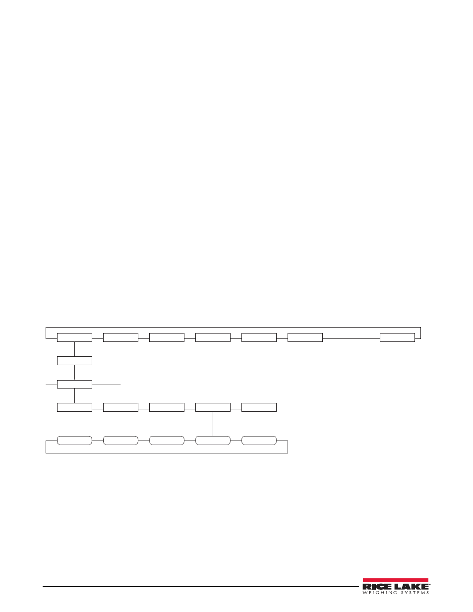
SCALES
SERIAL
FEATURE
PFORMT
SETPTS
DIG I/O
VERS
SCALE 1
CALIBR
WZERO
WVAL
WSPAN
WLIN
REZERO
POINT 4
POINT 5
POINT 1
POINT 2
POINT 3
Figure 5-5. Calibration (CALIBR) Submenu