2 trimming the junction box, Calibration 11 – Rice Lake RailBoss Rail Scales - Installation Manual User Manual
Page 15
Calibration
11
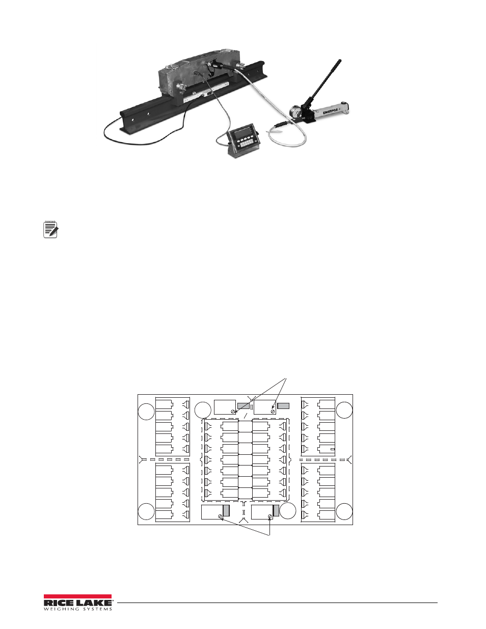
Figure 5-3. Indicator and Hydraulic Pump Attached to RailBoss Calibrator
4. Engage the pump by closing the release valve located on the side of the pump (turn clockwise).
5. Pump until weight reaches 30,000 lb and release pressure until weight returns to zero.
6. Repeat steps 4 & 5 two more times before attempting to calibrate.
Note
Hydraulic cylinders tend to bleed down at a slow rate.
If weight does not stabilize, repeat step 4-6.
7. Calibrate the indicator to match the scale’s 30,000 lb. load (see Section 5.1). If weight is not stable, repeat
Step 4.
8. Repeat Steps 1 - 7 on each RailBoss rail.
9. Once calibration is complete on all RailBoss rails, disconnect the hydraulic pump and indicator.
5.2
Trimming the Junction Box
Trimming is a process of equalizing the output from multiple individual load cells. If needed, load cell output can
be individually trimmed with potentiometers. Whenever a substantial amount of trim (more than 5% of normal
output), seems necessary to equalize output, check for other possible problems. The best trim is always the least
amount of trim. When all errors except cell mismatch and cable extensions or reductions have been corrected,
continue with the trimming
JP4
JP2
PT4
PT3
JP3
PT1
EXP
PT2
JP1
1
CELL4
1
CELL1
1
CELL3
1
CELL2
IND
-EX
-SI
SHD
+SI
+EX
M
R
N
I
-SI
S2 C
I
A
G
+EX
+SI
-SI
SHD
-EX
I
S
G
A
L
T
+SI
M
S
I
N
L
T
R
+EX
-EX
-SI
SHD
+SI
+EX
+SI
-EX
-SI
SHD
-EX
SHD
+SE
-SE
+EX
Potentiometers
Jumper Locations
JP1 and JP2
Shaded
Jumper Locations
JP3 and JP4
Shaded
Potentiometers
Figure 5-4. Signal Trim Main Board