2 cable grounding, 3 920i wiring, 2 cable grounding 3.3 920i wiring – Rice Lake RailBoss Rail Scales - Installation Manual User Manual
Page 11
Junction Box Installation
7
3.2
Cable Grounding
Except for the power cord, all cables routed through the
cord grips should be grounded against the indicator
enclosure.
1. Use the lock washers, clamps, and kep nuts
provided in the parts kit to install grounding
clamps on the enclosure studs adjacent to cord
grips. Install grounding clamps only for cord
grips that will be used; do not tighten nuts.
2. Route cables through cord grips and grounding
clamps to determine cable lengths required to
reach cable connectors.
3. Strip the insulation and foil from the cable half
an inch (15 mm) past the grounding clamp (see
Figure 3-2). Fold the foil shield back on the
cable where the cable passes through the
clamp. Ensure silver (conductive) side of foil is
turned outward for contact with the grounding
clamp.
Cord grip
Insulated cable
Foil (silver-side out)
Grounding clamp
Shield wire (cut)
Length of foil before folding
back on cable insulation
Cut insulation here
for foil-shielded cables
NOTE: Install lockwashers
first, against enclosure,
under grounding clamp
Figure 3-2. Grounding Clamp Attachment
4. Cut the shield wire just past the grounding
clamp. Shield wire function is provided by
contact between the cable shield and the
grounding clamp.
5. Route stripped cables through cord grips and
clamps. Ensure shields contact grounding
clamps as shown in Figure 3-2. Tighten
grounding clamp nuts.
6. Finish installation using cable ties to secure
cables inside of indicator enclosure.
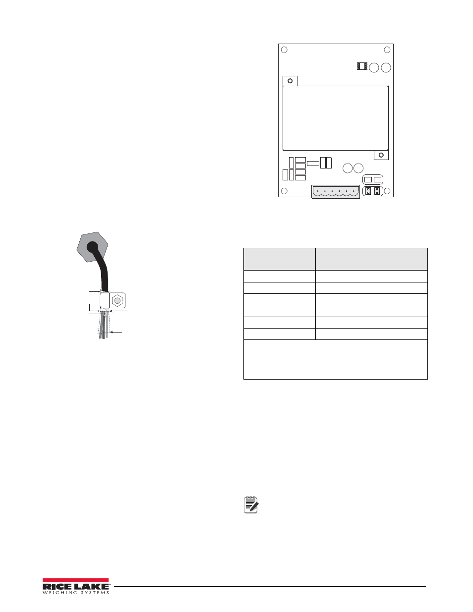
3.3
920i Wiring
1. Route the cable through the cord grip and
g r o u n d t h e s h i e l d w i r e a s d e s c r i b e d i n
Section 3.2.
2. Remove connector J1 from the A/D card. The
connector plugs into a header on the A/D card
(see Figure 3-3). Wire the load cell cable from
the load cell or junction box to connector J1 as
shown in Table 3-3.
SIG+
SIG–
SEN+
SEN–
EXC+
EXC–
J1
JP2
JP1
Figure 3-3. Single-Channel A/D Card
Table 3-3. A/D Card Pin Assignments
A/D Card
Connector Pin
Function
1
+SIG
2
–SIG
3
+SENSE
4
–SENSE
5
+EXC
6
–EXC
•
For 6-wire load cell connections to connector J1, remove
jumpers JP1 and JP2.
•
For 6-wire load cell connections to connector J2 (dual A/D
cards), remove jumpers JP3 and JP4.
3. If using 6-wire load cell cable (with sense
wires), remove jumpers JP1 and JP2 before
r e i n s t a l l i n g c o n n e c t o r J 1 . F o r 4 - w i r e
installation, leave jumpers JP1 and JP2 on. For
6-wire load cell connections on dual-channel
A/D cards, remove jumpers JP3 and JP4 for
connections to J2.
4. When connections are complete, reinstall load
cell connector on the A/D card and use two
cable ties to secure the load cell cable to the
inside of the enclosure.
Note
Because cables could be exposed to water or
other liquids, bend a short downward loop in
all cables near the cord grips so any fluids
draining down the cables will drip off before
reaching the junction box.