Rice Lake MSI6260cs Digital Crane Scale Operator Manual User Manual
Page 7
MSI-6260CS Crane Scale™
•
User Guide Page 7
MEASUREMENT SYSTEMS INTERNATIONAL
Rev 1 4/14/06 for SW Ver 5-xx
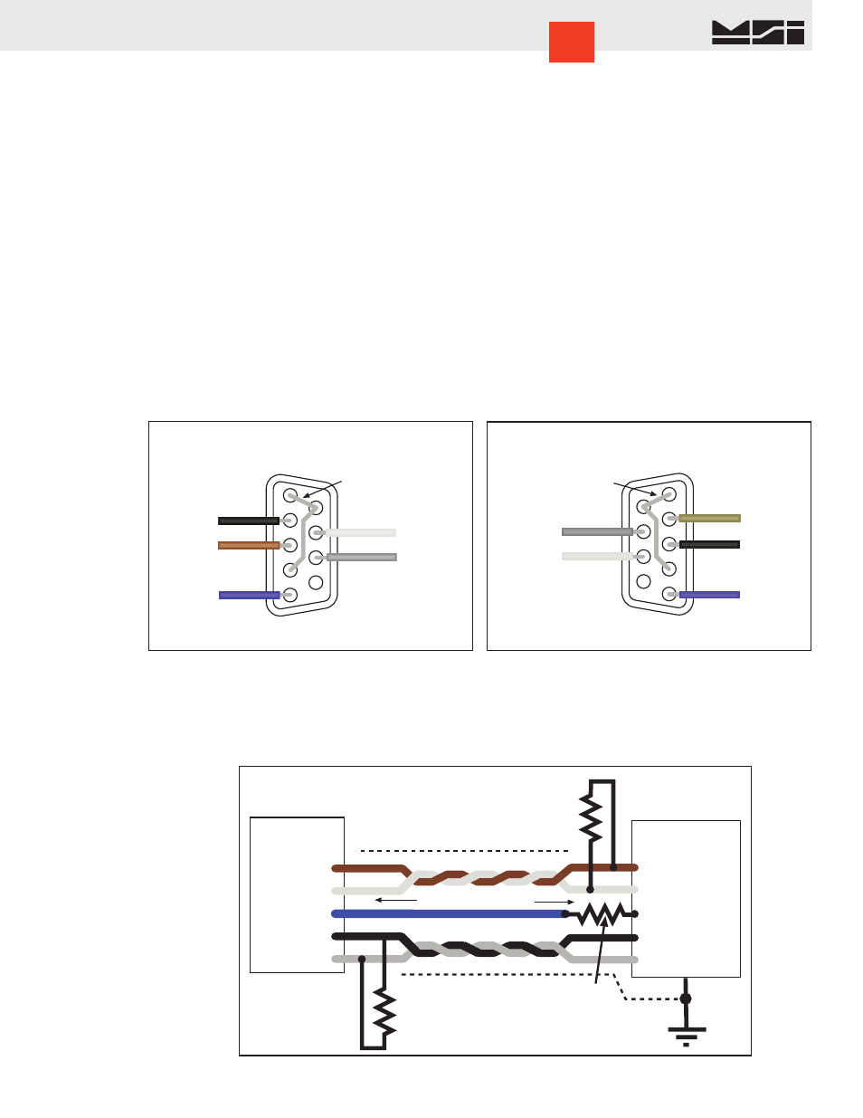
COMM PORT
The 6260CS has a single Comm Port allowing access to the embedded CellScale through the Terminal Access
Mode. The Terminal Access Mode is used for setup and calibration of the 6260CS by providing an interface
to the embedded CellScale. This Comm Port is not intended for output use as it is usually impractical to use
a cable connected port on a Crane Scale. However, in fixed scale applications, the Comm Port can be used to
drive printers, scoreboards, and any other serial peripheral.
Comm Port Cables
The 6260CS comes standard with one Comm Port Cable wired for RS-232 (MSI P/N 501705-0001) following
the AT standard for 9 pin serial cables (DCE). An unterminated cable is available (MSI P/N 12023) if you wish
to wire your own serial cable for RS-232 or RS-422 or RS-485.
Comm Port Cable Color Code RS-232
Brown – Transmit output from CellScale, connect to receive of DTE.
Black – Receive input to CellScale, connect to transmit of DTE.
Grey – CTS Input to CellScale. Connect to RTS or RTR output of DTE.
White – RTS/RTR output from CellScale. Connect to CTS input of DTE.
Blue – Signal Ground
Drain Wire – Connect to metal shell.
CellScale
COMM PORT
Pin 1- TD+
Pin 2 - TD-
Pin 3 - GND
Pin 4 - RD+
Pin 5 - RD-
TD+
TD-
RD+
RD-
GND
CHASSIS GND
485 Termination
Resistor. 120
Ω 1/4W
Final receiver only.
485 Termination
Resistor. 120
Ω 1/4W
Final receiver only.
Terminate Shield
at only one end.
Ground Reference
Resistor. 100
Ω 1/2W
At all receivers.
Shield
Shield
RS-485/422 Full Duplex Connection
Remote Device
Up to 1000 meters
BRN
WHT
BLUE
BLK
GREY
RS-422/485 Operation
RS-422 and RS-485 serial connections are used when long wire runs are necessary. The 485 spec covers cable
runs up to 4000’. 422 and 485 are differential transmissions and require twisted pair wiring to achieve common
and normal mode rejection. Although short runs of 422/485 cabling is often just two wires, a ground reference
is required. Usually the ground reference is connected through resistors to prevent ground differential cur-
1
2
3
4
5
6
7
8
(NC) 9
Brown (TD)
Black (RD)
Blue (GND)
Grey (CTS)
White (RTS)
Jumper 1-6-4
RS-232 DCE
9-Pin Female ‘D’
Solder Cup View
Standard wiring for direct
9000 to Computer connection
1
2
3
4
5
6
7
8
9 (NC)
Brown (TD)
Black (RD)
Blue (GND)
Grey (CTS)
White (RTS)
Jumper 1-6-4
RS-232 DTE
9-Pin Male ‘D’
Solder Cup View
Wiring for direct 9000 to
Printer/Scoreboard connection