1 cable grounding, 2 load cells, 3 serial communications – Rice Lake IQ plus 590-DC Installation Manual User Manual
Page 10
6
IQ plus 590-DC Installation Manual
2.3.1
Cable Grounding
Except for the power cord, all cables routed through
the cord grips should be grounded against the
indicator backplate. Do the following to ground
shielded cables:
•
Use the lockwashers, clamps, and kep nuts
provided in the parts kit to install grounding
clamps on the backplate studs adjacent to cord
grips. Install grounding clamps only for cord
grips that will be used; do not tighten nuts.
•
Route cables through cord grips and grounding
clamps to determine cable lengths required to
reach cable connectors. Mark cables to remove
insulation and shield as described below:
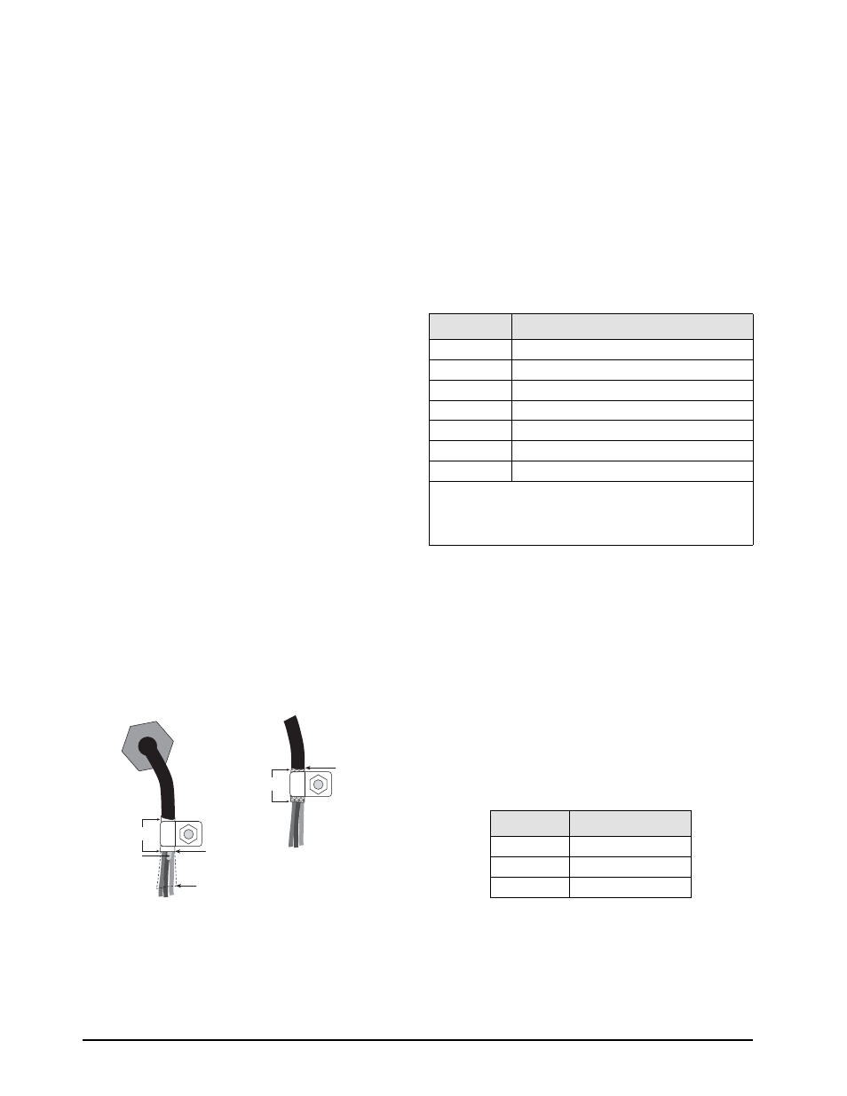
• For cables with foil shielding, strip insulation
and foil from the cable half an inch (15 mm)
past the grounding clamp (see Figure 2-2).
Fold the foil shield back on the cable where
the cable passes through the clamp. Ensure
silver (conductive) side of foil is turned
outward for contact with the grounding
clamp.
• For cables with braided shielding, strip cable
insulation and braided shield from a point just
past the grounding clamp. Strip another half
inch (15 mm) of insulation
only
to expose the
braid where the cable passes through the
clamp (see Figure 2-2).
•
For load cell cables, cut the shield wire just past
the grounding clamp. Shield wire function is
provided by contact between the cable shield
and the grounding clamp.
•
Route stripped cables through cord grips and
clamps. Ensure shields contact grounding
c l a m p s a s s h ow n i n F i g u r e 2 - 2 . Ti g h t e n
grounding clamp nuts.
•
Finish installation using cable mounts and ties to
secure cables inside of indicator enclosure.
Figure 2-2. Grounding Clamp Attachment for Foil-Shielded
and Braided Cabling
NOTE: A grounding screw is provided on the indicator
backplate for connecting a grouding wire (see Figure 2.4
on page 7).
2.3.2
Load Cells
To attach cable from a load cell or junction box,
remove connector J1 from the board. The connector
plugs into a header on the board. Connect cable from
the load cell or junction box through the load cell
cable cord grip to connector J1 as shown in Table 2-1.
If using 6-wire load cell cable (with sense wires),
remove jumpers JP1 and JP2 before reinstalling
connector J1 (see Figure 2-3 on page 7). For 4-wire
installation, leave jumpers JP1 and JP2 on.
When connections are complete, reinstall connector
J1 on the board.
2.3.3
Serial Communications
To attach serial communications cables, remove
connector J2 from the board (see Figure 2-3 on page
7). Connect communications cable through cord grip
to connector J2 as shown in Table 2-2.
Once cables are attached, reconnect J2 to the header
on the board.
The IQ plus 590-DC serial port supports full duplex
RS-232 communications for connections to printers,
PCs, and other attached devices. See Section 3.0 on
page 11 for general configuration information; see
Section 3.2.4 on page 19 for serial port configuration.
Cord grip
Insulated cable
Foil (silver side out)
Grounding clamp
Shield wire (cut)
Length of foil before folding
back on cable insulation
Cut insulation here
for foil-shielded cables
Braid
Cut insulation here
for braided cables
NOTE: Install lockwashers
first, against backplate,
under grounding clamp
J1 Pin
Function
1
+SIG
2
–SIG
3
+SENSE
4
–SENSE
5
SHIELD (see NOTE below)
6
+EXC
7
–EXC
NOTES:
• SHIELD wire connection not used. Use grounding
procedure described in Section 2.3.1 on page 6.
• For 6-wire connections, remove jumpers JP1 and JP2.
Table 2-1. J1 Pin Assignments
J2 Pin
Function
1
RS-232 TxD
2
RS-232 Ground
3
RS-232 RxD
Table 2-2. J2 Pin Assignments