Hazardous area, Inside of enclosure – Rice Lake EL232 XPCD Explosion Proof Remote Serial Display User Manual
Page 7
3
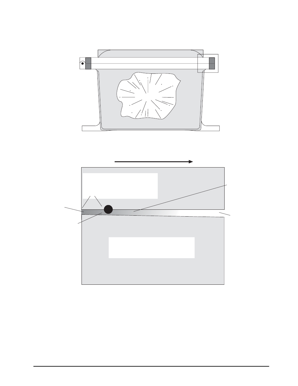
The design intent of an explosion proof enclosure is not to contain an explosion, but to control it. The flame
path is carefully controlled at the flanges. This insures that if an explosion occurs, any gases that escape will
be cooled to a temperature below the ignition point of any atmosphere specified within that enclosure’s
rating.
Explosion
HAZARDOUS
AREA
High temperature
gases
Cooling from
expansion of gas
(Boyle’s Gas Law)
The distance from the boundary of
the inside of the enclosure to the
gasket is known as the Flame Path.
This distance must be at least 1" for
Group C throughG.
INSIDE OF
ENCLOSURE
Lower
temperature
gases
Enlarged view
below
Propagation of gas due to
pressure from an internal
explosion
Gasket
For clarity, the slope of the flange
faces has been greatly enhanced
(Typically, the slope is .0015"/inch)
- 1010 Potted & Unpotted Single Point, Aluminum (58 pages)
- 120 Digital Weight Indicator (44 pages)
- 120 Plus Digital Weight Indicator (56 pages)
- 320IS Intrinsically-Safe Digital Weight Indicator - Installation Manual (76 pages)
- 320IS Intrinsically-Safe Digital Weight Indicator - Timer Relay Instruction Sheet (2 pages)
- 320IS Intrinsically-Safe Digital Weight Indicator - Battery Charging Instruction Sheet (2 pages)
- 320IS Intrinsically-Safe Digital Weight Indicator - I/O Module for Intrinsically Safe Systems Installation Manual (15 pages)
- 320IS Intrinsically-Safe Digital Weight Indicator - IS-6V Battery Pack Instruction Sheet (6 pages)
- 320IS Intrinsically-Safe Digital Weight Indicator - IS-EPS-100-240 Power Supply Instructions (6 pages)
- 320IS Plus Intrinsically Safe Digital Weight Indicator - Installation Manual (90 pages)
- 420 Plus HMI Digital Weight Indicator Installation Manual (60 pages)
- 420 Plus HMI Digital Weight Indicator Operator Card (3 pages)
- 420 Plus Digital Weight Indicator - 7.5V DC-to-DC Power Supply Installation (4 pages)
- 420 Plus Digital Weight Indicator - IQ plus 355 - 390-DC - 590-DC & 420 Plus Quick Connector Cable Installation Instructions (1 page)
- 480 Legend Series Digital Weight Indicator Installation Manual (68 pages)
- 480 Legend Series Digital Weight Indicator Operator Card (1 page)
- 480 Panel Mount Option (4 pages)
- 520 Analog Output Card Installation (2 pages)
- 520 Digital Weight Indicator Operator Card (4 pages)
- 520 HMI Digital Weight Indicator Installation Manual (98 pages)
- 520 HMI Digital Weight Indicator Manual - BCD Option (18 pages)
- 520 Configurable Weight Indicator - Remote I/O Indicator Interface Installation and Programming Manual (31 pages)
- 520 Configurable Weight Indicator - ControlNet Interface Installation and Programming Manual (23 pages)
- 520 Configurable Weight Indicator - DeviceNet Interface Installation and Programming Manual (21 pages)
- 520 Configurable Weight Indicator - Ethernet Interface Installation and Configuration Manual (38 pages)
- 520 Configurable Weight Indicator - EtherNet/IP Interfac Installation and Programming Manual (26 pages)
- 520 Configurable Weight Indicator - Profibus DP Interface Installation and Programming Manual (21 pages)
- 550-10-1 Digital Chair Scale - Operation Manual (26 pages)
- 550-10-1 Digital Chair Scale - Technical Manual (34 pages)
- 590-AG Livestock Digital Weight Indicator (56 pages)
- 65059 Mild Steel 3-Module Kit - RL50210 Load Cell Mounting Kit Installation Guide (13 pages)
- 720i Programmable Indicator/Controller - 6V DC-to-DC Power Supply Installation Instructions (4 pages)
- 720i Programmable Indicator/Controller - Installation Manual (122 pages)
- 720i Programmable Indicator/Controller - Operator Card (4 pages)
- 720i Programmable Indicator/Controller - Analog Output Card Installation Instructions (4 pages)
- 720i Programmable Indicator/Controller - CW-90/90X - iQUBE2 - LaserLT WLAN Installation Instructions (12 pages)
- 720i Programmable Indicator/Controller - USB Interface Card Installation Instructions (2 pages)
- 820i Programmable Indicator/Controller - Installation Manual (112 pages)
- 820i Programmable Indicator/Controller - Panel Mount Enclosure Installation Instructions (6 pages)
- 880 Performance Series Indicator/Controller Operators Manual (36 pages)
- 880 Performance Series Indicator/Controller Technical/Service Manual (120 pages)
- 880 Performance Series Panel Mount Indicator/Controller - Adapter Panel Installation (4 pages)
- 880 Performance Series Panel Mount Indicator/Controller - Analog Output Card Option Installation Manual (6 pages)
- 880 Performance Series Panel Mount Indicator/Controller - DeviceNet Interface Option Installation and Programming Manual (28 pages)
- 880 Performance Series Panel Mount Indicator/Controller - EtherNet/IP Interface Option Installation and Programming Manual (32 pages)