6 digital inputs, 7 relay contact outputs, 8 board removal – Rice Lake 320IS Plus Intrinsically Safe Digital Weight Indicator - I/O Module for Intrinsically Safe Systems Installation Manual User Manual
Page 9
Installation
5
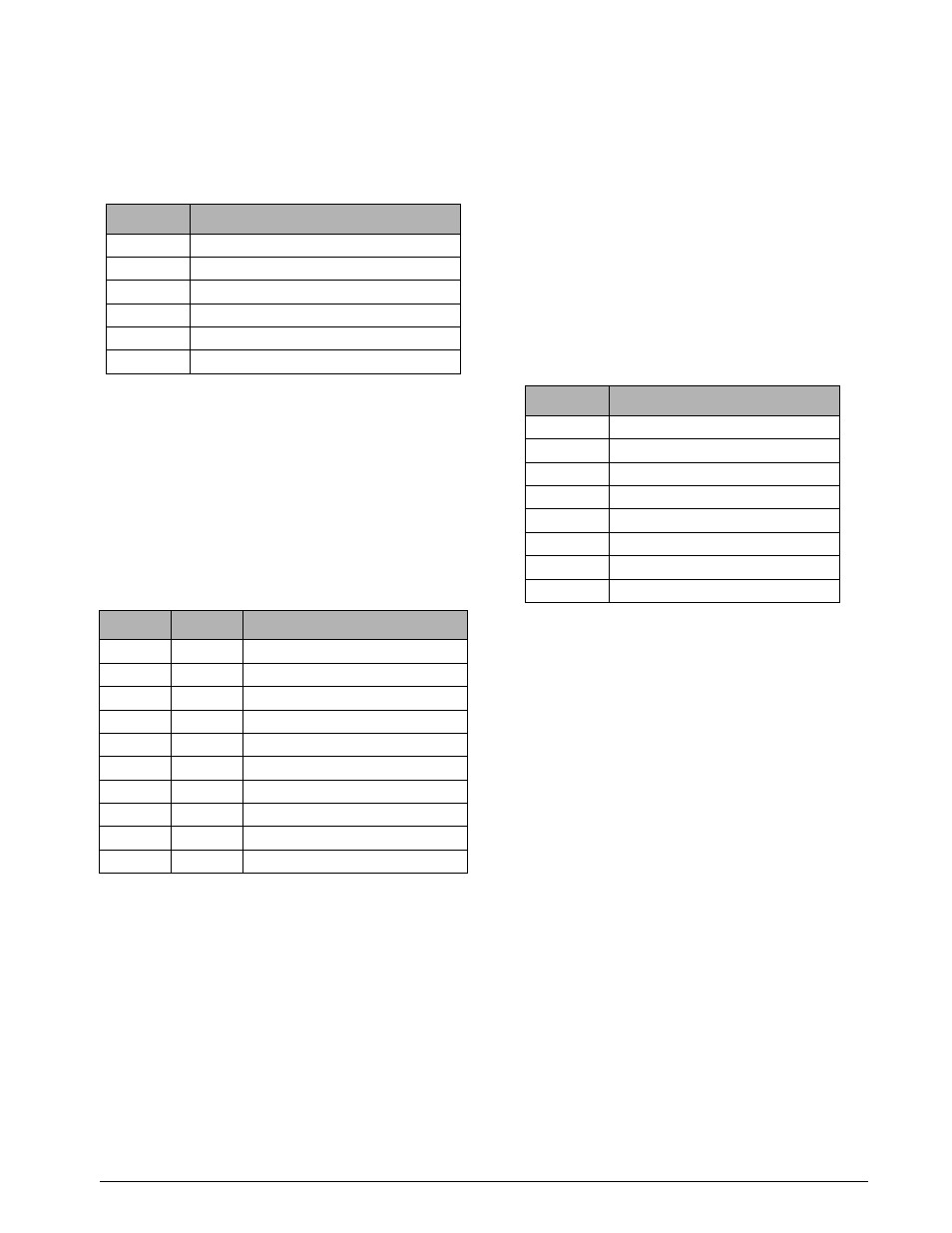
The analog output port is powered by an isolated
DC-DC converter. The outputs available on connector
CN1 are listed in Table 2-8 below. See Figure 2-1 on
page 2 for the location of CN1 and DIP switches.
2.6
Digital Inputs
The
I/O Module
has four digital inputs that can be
used to control pre-defined operations in the indicator.
Table 2-9 outlines the various functions for the digital
inputs.
Digital inputs are available on connector CN4 (see
Figure 2-1 on page 2). All inputs are individually
isolated via optocouplers. Table 2-9 outlines the pin
connections for CN4.
The digital inputs are designed to receive 0-24V/TTL
signals on the incoming lines. Care should be taken to
apply the right DC polarity. Pins 9 and 10 (+5V and
DGND) can be used to supply power to the digital
inputs. Maximum current draw should not exceed
0.25A.
See the applicable indicator installation manual for
information on checking current digital input states.
2.7
Relay Contact Outputs
The
I/O Module
features four relay contact outputs,
which default to open. This allows switching of
maximum +30VDC, 5A or 250VAC, 5A for each of
the four digital channels.
T h e r e l a y c o n t a c t o u t p u t s a r e c o n t r o l l e d b y
user-configurable setpoints. The setpoint values and
operating parameters can be defined in the SETPNT
m en u o f th e h o st i nd i ca t o r. S e e th e i nd i ca t or
installation manual for information on configuring
setpoints.
Table 2-10 show pin connections for CN5 of the
I/O
Module
board.
The states of the relay contacts are indicated by LEDs
LD1–LD4 (see Figure 2-1 on page 2). When an LED
is lit, the contacts of the corresponding relay are
closed. See the applicable indicator installation
manual for information on checking relay contact
functionality.
2.8
Board Removal
If the
I/O Module
’s main board must be removed, use
the following procedure:
1. Disconnect power to the board.
2. Unplug all connectors.
3. Remove the six screws holding the main
board, then lift the board out of the enclosure.
To replace the board, reverse the above procedure. Be
sure to reinstall cable ties to secure all cables inside
the enclosure.
Pin
Name
1
Ground (Analog Output 1 Common)
2
Analog Output 1 (current)
3
Analog Output 1 (voltage)
4
Analog Output 2 (current)
5
Analog Output 2 (voltage)
6
Ground (Analog Output 2 Common)
Table 2-8. CN1 Connectors
Pin
State
Description
1
Hi
Digital Input 1 (+V)
2
Low
Ground 1 (–V)
3
Hi
Digital Input 2 (+V)
4
Low
Ground 2 (–V)
5
Hi
Digital Input 3 (+V)
6
Low
Ground 3 (–V)
7
Hi
Digital Input 4 (+V)
8
Low
Ground 4 (–V)
9
Hi
+5V
10
Low
DGND
Table 2-9. CN4 Connections
Pin
Description
1
Output 1_A
2
Output 1_B
3
Output 2_A
4
Output 2_B
5
Output 3_A
6
Output 3_B
7
Output 4_A
8
Output 4_B
Table 2-10. CN5 Connections