3 rs-485 communications, 4 rs-422 communications, 5 20ma current loop – Rice Lake 320IS Plus Intrinsically Safe Digital Weight Indicator - I/O Module for Intrinsically Safe Systems Installation Manual User Manual
Page 8: 5 analog outputs, Rs-485 communications, Rs-422 communications, 20ma current loop
4
I/O Module Installation Manual
2.4.3
RS-485 Communications
To attach a PC or other device to the
I/O Module
’s
RS-485 ports, select RS-485 standard in the indicator
SERIAL menu for the desired port (EDP and/or
printer). EDP and printer ports should be configured
separately. See Table 2-4 below for information on
connecting RS-485.
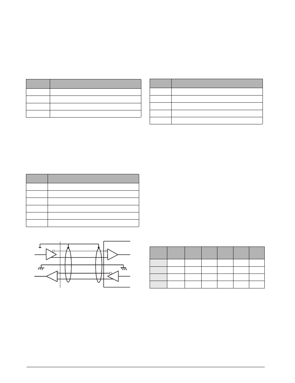
2.4.4
RS-422 Communications
To attach a PC or other device to the
I/O Module
’s
RS-422 ports, select RS-422 standard in the indicator
SERIAL menu for the desired port (EDP and/or
printer). EDP and printer ports should be configured
separately. See Table 2-5 below for information on
connecting RS-422 communications.
Figure 2-4. Typical RS-422 Wiring Paths
2.4.5
20mA Current Loop
To attach a PC or other device to the
I/O Module
’s
20mA ports, select current loop (CL) standard in the
indicator SERIAL menu for the desired port (EDP
and/or printer). EDP and printer ports should be
configured separately. See Table 2-6 below for
information on connecting 20mA current loop.
2.5
Analog Outputs
The
I/O Module
uses two 16-bit isolated analog output
channels with 4-20mA and voltage (0-5V/±5V/0-10V/
±10V) outputs supplied from a DC/DC converter. The
output voltage ranges are DIP-switch selectable (see
Figure 2-1 on page 2). Analog output configuration is
done via setup mode in the indicator used with the
I/O
Module
(see the applicable indicator installation
manual).
the analog output circuitry consists of two identical
channels that can be assigned to gross or net weight
values. The analog output can be configured to
operate as either current or voltage outputs. the
voltage output range is selected by configuring DIP
switches SW1 (1-6) for channel 1 and SW2 (1-6) for
channel 2 (see Figure 2-1 on page 2).
Table 2-7. Output Range Configuration
Pin
Description (Sign)
1
Signal Ground (GND)
2 - 6
—
7
RS-485 line (A)
8
RS-485 line (B)
Table 2-4. RS-485 Connections (CN2 and CN3)
Pin
Description (Sign)
1
Signal Ground (GND)
2 - 4
—
5
RS-422 input (R+)
6
RS-422 input (R-)
7
RS-422 output (T+)
8
RS-422 output (T-)
Table 2-5. RS-422 Connections (CN2 and CN3)
8
7
1
6
5
I/O Module
Pin
Description (Sign)
1
Signal Ground (GND)
2
Isolated Ground (GNDx)
3
Receive Data (RCL)
4
Transmit Data (TCL)
5 - 8
—
Table 2-6. 20mA Current Loop Connections (CN2 and
CN3)
Range
SW1-1
SW2-1
SW1-2
SW2-2
SW1-3
SW2-3
SW1-4
SW2-4
SW1-5
SW2-5
SW1-6
SW2-6
0–5V
OFF
OFF
OFF
ON
X
X
0–10V
OFF
ON
X
OFF
ON
X
±5V
ON
OFF
OFF
OFF
ON
X
±10V
ON
OFF
ON
OFF
OFF
ON