0 installation, 1 unpacking and assembly, 2 enclosure disassembly – Rice Lake 320IS Plus Intrinsically Safe Digital Weight Indicator - I/O Module for Intrinsically Safe Systems Installation Manual User Manual
Page 6: 3 installation of the i/o module, Installation, Caution, Warning, Immediately after unpacking, visually inspect the, See figure 2-1 fo r port locations, I/o module
2
I/O Module Installation Manual
2.0
Installation
This section describes procedures for connecting the
analog and digital I/Os, fiber optic and serial
communication cables to the
I/O Module
.
•
Use a wrist strap to ground yourself and protect
components from electrostatic discharge (ESD)
when working inside the indicator enclosure.
•
It is mandatory to return the
I/O Module
to Rice
Lake Weighing Systems for circuit board level
service. Component level repair is not permitted on
UL-approved equipment by anyone other than the
manufacturer.
2.1
Unpacking and Assembly
Immediately after unpacking, visually inspect the
I/O
Module
to ensure all components are included and
undamaged. The shipping carton should contain the
I/O Module
, this manual, and a parts kit. If any parts
w ere d am a ge d i n s hip m e nt, n ot ify R ic e L ak e
Weighing Systems and the shipper immediately.
2.2
Enclosure Disassembly
The
I/O Module
enclosure must be opened to connect
cables for load cells, communications, and power.
The
I/O Module
has no on/off switch.
Before opening the unit, ensure the
power cord is disconnected.
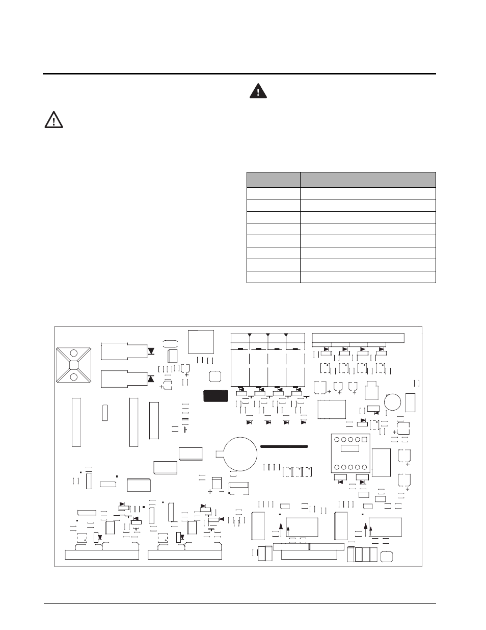
2.3
Installation of the I/O Module
The following section describes the wiring of various
ports of the
I/O Module
. Table 2-1 below lists the
connectors of the main board of the
I/O Module
. See
Figure 2-1 for port locations.
Figure 2-1. I/O Module Board
Caution
Connector
Description
CN1
Analog Outputs
CN2
EDP Port
CN3
Printer Port
CN4
Digital Inputs
CN5
Relay Outputs
CN8
DC Power
Optical Input
Light Port
Optical Output
Light Port
Table 2-1. I/O Module Wiring Ports
Warning
R
3
4
R22
Q1
C27
R65
Q3
R
35
R31
R55
R6
R39
Q5
TVS3
C10
C11
R14
R12
R15
D11
R42
R43
R45
R8
OP4
Q8
R48
C14
TVS4
R17
R21
D8
R32
CN
6
D5
Q9
R26
R47
R20
R19
R51
R18
R53
C25
R37
Q4
D6
Q2
C18
R57
R58
R62
R63
R25
C26
R10
R11
C15
C28
C29
C36
C6
C7
C1
R1
R3
U12
C21
C24
R23
D7
R
3
6
U9
R56
IF-D91
PD1
C16
C17
C19
D4
R2
8
C44
U15
R59
R60
R61
R54
CN7
C35
C9
C8
R5
R7
R1
3
LD1
LD2
Q6
D9
D10
R38
R40
R41
U3
S
W1
R9
OP2
OP
3
LD4
Q7
D12
R44
R46
TVS6
TV
S
2
U5
C12
C1
3
+
C47
R64
D1
Z1
U17
C34
C41
C40
D17
R4
D14
D15
R50
R52
R16
C5
CN8
MH1
OP
6
C43
U14
J5
U10
R33
J4
IF-E96
LD5
U7
GD1
C30
C31
U6
U2
K2
K1
OP7
K4
TV
S
5
OP1
OP8
OP9
R4
9
C4
C3
C20
R29
C23
R30
C32
+
C46
C2
CN2
TVS1
U8
C22
D3
U13
B1
LD3
C33
U16
Y1
GD2
U4
S
W2
U1
D2
T1
C45
F1
U18
R2
CN4
D13
D16
U11
OP5
U19
1
J1
R27
K3
OP10
T1A
CN1
CN
3
CN5
2
1
2
1
SO16
1A
2B
1
1
2
N
O
1
2
4A
3
4
5
3
4
5
6
6
HI
HI
LO
LO
N
O
1
2
1
2
HI
3
4
5
3
4
5
+5V
6
6
1
DGND
3
2
4
Tx
5
6
Rx
7
TD(A)
1
DGND
2
3
4
Tx
5
6
Rx
7
TD(A)
8
C
H
1
V+
I+
Gnd-
2
1
20mA
1
LIGHT PORT
RS-232/485
SOW16
1B
2A
3A
3B
4B
LO
HI
LO
AGND
PWR
GND
DGND
IGND
Rx
8
Tx
RD(B)
TD(B)
1
2
20mA
Rx
RD(A)
RD(B)
TD(B)
Tx
1
V+
I+
Gnd-
ON
1
C
H
ON
RS-232/485
OPTICAL OUTPUT
DGND
DIGITAL OUTPUTS - RELAY CONTACTS
DIGITAL INPUTS +5 VOLTS
RD(A)
IGND
OPTICAL INPUT
RICE LAKE WEIGHING SYSTEMS
U20