0 configuration, Configuration – Rice Lake 320IS Plus Intrinsically Safe Digital Weight Indicator - I/O Module for Intrinsically Safe Systems Installation Manual User Manual
Page 13
Configuration
9
3.0
Configuration
Configuration of the external
I/O Module
is done through the SETUP menu of the attached indicator acting as the
master device.
All operating parameters are stored in the host indicator’s EEPROM memory, and can be edited after placing the
indicator in SETUP mode. See the indicator installation or operation manual for instructions on editing
configuration parameters.
The
I/O Module
works as the "slave" device of the indicator and will not work as a stand-alone unit. After both
the indicator and
I/O Module
are powered up, the module attempts to communicate with the indicator through the
fiber optic port and all necessary working parameters are sent to the
I/O Module
. All inputs and outputs function
as peripheries of the indicator. Communication must remain constant between the two devices for data to be
transferred through the various ports.
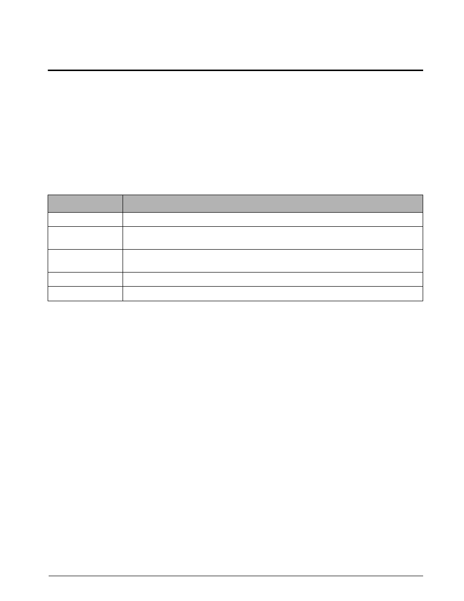
See Table 3-1 for parameters that are sent to the
I/O Module
during power up.
Data Type
Parameters
ID
Device code, Revision, Version text
EDP, Print Ports
Baud Rate, Parity, Stop Bits, End of Line Delay, Termination, Port Interface, Address for RS-485
Operation
Analog Output
Output (voltage, current), Error Action (full scale, hold, zero scale), Tweak Zero Value, Tweak Span
Value
Digital Output
Output (On/Off) Enable Mask
Digital Input
Enable Mask
Table 3-1. Configuration Parameters Sent to I/O Module