Off-road gearing, On-road speed runs, Troubleshooting your speed-t – Losi LOSB0101 User Manual
Page 14
26
27
®
®
Standard Ball Differential Adjustment:
(optional, not included)
Never allow the diff to slip; that’s what the slipper is for. Before
trying to adjust your diff, you need to tighten the slipper until
the spring is fully compressed. Next set the diff setting so it is
on the tight side and break the diff in. How you break the diff
in is by placing one tire on the tabletop while the other tire is
off of the tabletop. Then give the truck about ¼ throttle for 30
seconds. Then do the same thing but place the opposite tire on
the tabletop while the other tire is in the air and give the truck
¼ throttle for another 30 seconds. Once that is done you can
set the diff. The diff setting will loosen up a little while it is still
breaking in and it is important for you to break the diff in prior
to driving the truck. Hold the spur gear and right rear tire, then
try turning the left rear tire forward. It should be very difficult
to turn the left rear tire. If the tire turns easily, the diff is too
loose. To tighten the diff, line up the slot in the diff screw with
the groove in the left out drive. Place the 1/16” Allen wrench
through both of these slots. This will lock the diff screw and the
out drive together. While holding the Allen wrench in place,
turn the right rear tire forward about 1/8 of a turn. Check the
differential adjustment again and repeat the tightening process
as necessary until the differential is no longer slipping. Do not
forget to reset the slipper setting. See “Slipper Adjustment” on
page 24, and then continue from here. The final differential
adjustment check should be made by placing the truck on
carpet, grass, or asphalt and “punching” (quickly applying)
the throttle. The differential should not slip. If it does, tighten
the diff in 1/8-turn increments as described above until the
slippage stops. Once the diff has been adjusted, it should still
operate freely and feel smooth. If the diff screw starts to get
tight before the diff is close to being adjusted properly (based
on slip), the diff should be disassembled and inspected; you
may have a problem with the differential assembly.
Breaking in the Differential:
While holding the chassis with only the left side tires firmly
on the ground, give the truck about one quarter throttle, for
10 seconds. The right side tires should spin freely during this
time. Repeat this with only the right side tires held firmly to the
ground, allowing the left tires to spin. Feel the differential (diff)
action and tighten slightly, if necessary. The differential should
have a tight, thick feel when rotating it after final adjustment.
CAUTION!
YOUR DIFFERENTIAL SHOULD NEVER BE ALLOWED TO SLIP
WHEN RUNNING (A SLIPPING DIFFERENTIAL CREATES A
“BARKING” SOUND). IF IT DOES, STOP IMMEDIATELY AND
TIGHTEN TO PREVENT DAMAGE.
Adjusting Gear Mesh
Incorrect gear mesh is the most common cause of stripped spur
gears. To set the gear mesh, one method is to cut a narrow strip
of notebook paper and thread it in between the gears. Loosen
the motor screws and slide the motor and pinion gear into the
spur gear. Retighten the motor screws and then remove the
strip of paper. Or you can loosen the motor and carefully slide
the motor leaving a small amount of backlash (play) between
the spur and pinion gears. It should not be tight and if you look
up-close there should be slight movement of the spur before
contacting the teeth on the pinion gear.
Gear Ratio
Changing the gearing provides you a quick and easy way to
tune the Speed-T. Use the temperatures of both the Xcelorin
motor and your battery pack as a guide to gearing to your
environment. When the Motor is above 160-170 degrees
Fahrenheit or the batteries are above 125-135 degrees
Fahrenheit, these are both strong indications that you should
drop the pinion size smaller. This would be a lower gear ratio
or larger number for example from 11.25 to 12.40. Going up
a pinion size is called gearing higher or a small number for
example 11.25 to 10.6 and will increase power consumption
and allow more speed.
Use the following formula to calculate the overall ratio for
combinations not listed on the gear chart:
Spur Gear Size
Pinion Gear Size
X 2.43 = Final Drive Ratio
When using higher gear ratios, it is extremely important to
monitor the temperatures of the battery and motor. If the
battery is extremely hot, and/or the motor is so hot that you
cannot touch it, most likely you are over-geared and drawing a
lot of current.
The gear combination that comes on the Speed-T (20-tooth
pinion / 88-tooth Spur) provides high-speed running intended
for hard surfaces, and this gearing is not recommended for
off-road, running in grass or constant starting and stopping.
The following Gearing Tables will provide you a starting point
to gear the Speed-T for your desired running surface. Ambient
temperature and humidity along with the condition of your
equipment play a considerable role in performance.
Use the gear ratio charts and legend to aid in determining the
correct pinion and spur for your Speed-T.
Storage
When you are through running the model for the day
•
Blow it off with compressed air or use a soft bristled paint
brush to dust-off the vehicle.
•
Always disconnect and remove the battery from the
model whenever the model is stored. If the model will
be stored for a long time, then also remove the batteries
from the transmitter.
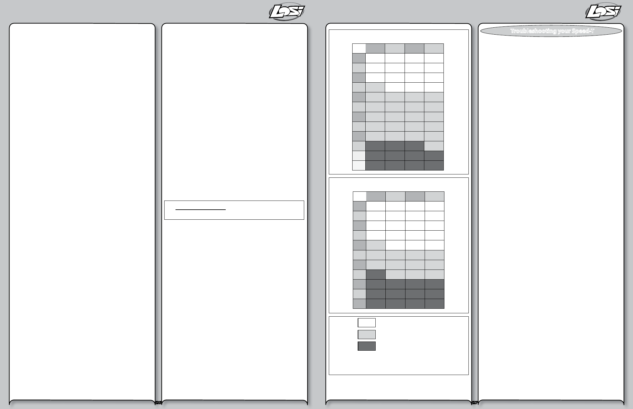
Off-Road Gearing
84
86
88
90
12
13
15
17
19
21
23
22
20
18
16
14
17.01
17.42
17.82
18.23
15.70
16.08
16.45
16.82
14.58
14.93
15.27
15.62
13.61
13.93
14.26
14.58
12.76
13.06
13.37
13.67
12.01
12.29
12.58
12.86
11.34
11.61
11.88
12.15
10.74
11.00
11.25
11.51
10.21
10.45
10.69
10.94
9.72
9.95
10.18
10.41
9.28
9.50
9.72
9.94
8.87
9.09
9.30
9.51
See Note 1
On-Road Speed Runs
84
86
88
90
15
17
19
21
23
22
20
18
16
14
14.58
14.93
15.27
15.62
13.61
13.93
14.26
14.58
12.76
13.06
13.37
13.67
12.01
12.29
12.58
12.86
11.34
11.61
11.88
12.15
10.74
11.00
11.25
11.51
10.21
10.45
10.69
10.94
9.72
9.95
10.18
10.41
9.28
9.50
9.72
9.94
8.87
9.09
9.30
9.51
24
8.51
8.71
8.91
9.11
Safe
Use Caution
Not Allowed
Safe
Use Caution
Not Allowed
Supplied Gear Ratio:
10.69
Note 1: If using 3S LiPo battery for off-road
do not use larger than a 18t pinion gear (Not Included).
Many questions are the result of simple user errors or minor
adjustments which are easily addressed. If after reading below
you cannot resolve your problem, then please call Horizon
Product Support at 1.877.504.0233.
Radio system does not work properly:
If the power light on the transmitter is not turning on, first
ensure the batteries are installed correctly. You should also
check that the batteries are good and/or if rechargeable are
fully charged. Replace them if needed. If the power light is
blinking, then the transmitter batteries are weak and should be
replaced. If the transmitter light is on but the radio is still not
responding, you may need to re-bind the transmitter to the
receiver. Please see page 16.
Short radio range:
If the radio range appears short, make sure the batteries are all
fully charged and/or are in good condition.
Steering works but the motor will not run:
The speed control may have gotten too hot and thermally shut
down (see page 18). Allow time for the speed control to cool.
If this is the problem and has happened a few times, consider
using a smaller pinion or a larger spur gear.
Check the transmission, do the rear wheels spin easily?
Check that a motor wire has not come loose.
Verify that the electronic speed control is plugged into the
throttle channel of the receiver.
Check using another battery. Contact Horizon support for
service instructions.
Steering servo does not work:
Check all wires, radio system, battery connectors, and the
battery pack.
Contact Horizon support for service instructions.
Motor runs backwards:
Looking directly at the end of the motor the wires attached to
the left most should be the Black wire, the center Blue, and the
far right should be White. If not please correct. If you are still
experiencing problems please contact Horizon support.
Motor starts running immediately after the battery has
been connected.
There may be internal ESC damage. Contact Horizon
Product Support.
Troubleshooting your Speed-T