Losi LOSB0101 User Manual
Page 10
18
19
®
®
Profile Overview
Profile #1 - “High Speed Performance”
Cutoff Voltage-
LiPo 3S
Brake/Reverse Role-
Forward only **
Motor Timing-
Normal
Initial Acceleration-
High **
Drag Brake-
Low
Brake-
Braking
Vehicle Speed-
Maximum
Reverse Speed-
(Not active)
Profile #2 - “Bashing Fun”
Cutoff Voltage-
No Cutoff (NiMH)
Brake/Reverse Role-
Forward with Pause then Reverse **
Motor Timing-
Normal
Initial Acceleration-
Medium **
Drag Brake-
Medium
Brake-
Medium
Vehicle Speed-
Medium
Reverse Speed-
Medium
Profile #3 settings (Default): “Low Speed - Beginner”
Cutoff Voltage-
No Cutoff (NiMH)
Brake/Reverse Role-
Forward with pause then Reverse **
Motor Timing-
Low
Initial Acceleration-
Low **
Drag Brake-
High
Brake-
High
Vehicle Speed-
Low
Reverse Speed-
Medium
** QPC cannot change
Selecting profiles:
Notice that Profile #3 is set from
the factory as the DEFAULT.
Overriding the Active Profile
There are three (3) saved profiles within the ESC, previously
described.
To override a setting within the active profile, select a saved
profile that resembles your needs, or make further changes
to the current profile. Review the QPC and set jumpers to
your choice. You must make a choice for each area of the
QPC, Cutoff Voltage, Brake, Drag Brake, Vehicle Speed, Reverse
Speed, and Motor Timing.
For example if you have the ESC active profile set to Profile #3
(Default) and would like a little more speed but change nothing
else, place the jumpers on the following choices.
Cut-off Voltage
NiMH
Brake
High
Drag Brake
High
Vehicle Speed
Medium (was Low)
Reverse Speed
Medium
Motor Timing
Low
Then follow the instructions for using the Quick
Programming Card. You can change one setting at a
time or any combination.
Making the above change is ONLY overriding the active profile.
At any time, you can reset the ESC to profile #3 and the active
profile is returned to the original profile #3 settings.
Selecting Profiles
1.
Turn the Transmitter on.
2.
Turn the vehicle on.
3.
With the ESC turned on and ready for operation, press
& hold the setup button until both the Yellow and Blue
LED flash.
4.
Release setup button.
5.
The status LEDs flash to indicate the current
profile setting.
LED status for each Profile below:
Profile 1
Yellow and Blue LED flash
Profile 2
Yellow, Blue and Green LED flash
Profile 3
Yellow, Blue, Green and Red Flash
(default setting)
6.
To make a change, quickly press the setup button,
which will advance you to the next profile.
7.
When you are finished, press and hold the setup
button 2 seconds, the 4 status LEDs will scroll
and the new selection will be stored to the active
memory of the ESC.
8.
If you do not press the setup button within 15
seconds, the 4 status LEDs will scroll to indicate you
are exiting programming. The ESC will return to
neutral and be ready for use without any change.
These stored settings, also referred to as “profiles,” are
defined here.
Modifying ACTIVE profile with the
Quick Programming Card (QPC)
The Xcelorin Quick Programming Card (QPC) is used to make
all adjustments to the active profile in your ESC. Any ACTIVE
profile can be modified.
Using the QPC you can set the following:
Cut-Off Voltage
•
NiMH (NiCd)
•
2S LiPo
•
3S LiPo
Braking Strength
•
Low
•
Medium
•
High
Drag Brake
•
Low
•
Medium
•
High
Vehicle Speed (By throttle limiting)
•
Lowest
•
Low
•
Medium
•
Maximum
Reverse Speed
•
Low
•
Medium
•
Maximum
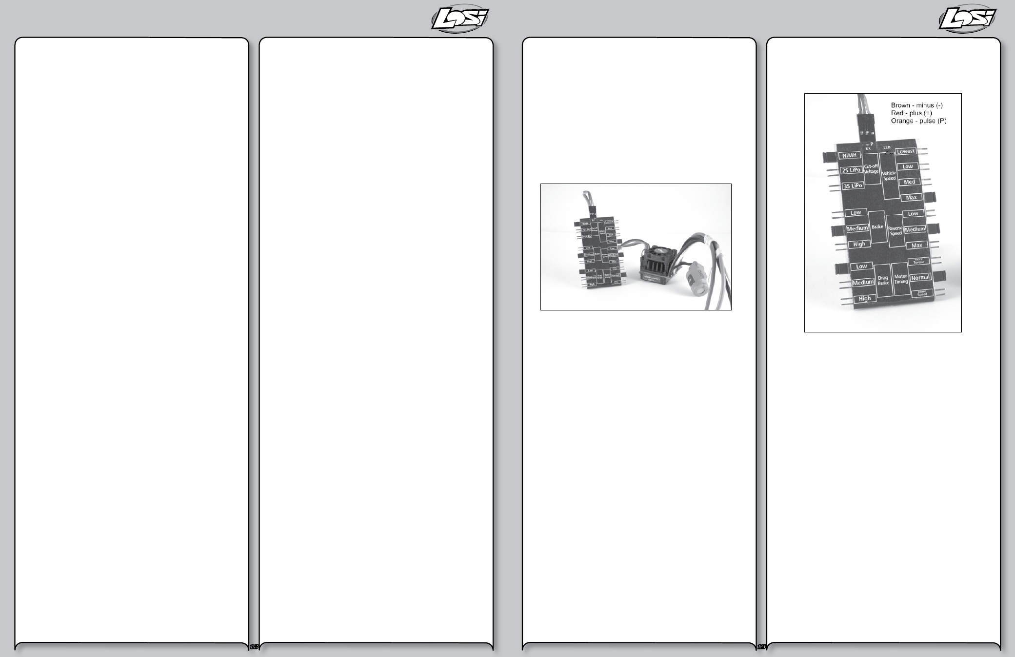
Using the Quick Programming Card
With the QPC in your hand and the back facing you, notice the
small jumper connectors. The jumpers are used to indicate
which function you want to activate.
To change the settings rearrange the small jumpers to the
desired settings.
To Upload to the ESC do the following:
1.
Ensure the transmitter and vehicle are turned off.
2.
Make sure a battery pack is installed that has some
charge in it.
3.
Connect the battery to the vehicle.
4.
Turn the power on to the ESC, wait for the Blue (or
Blue/Yellow) LED to come on.
5.
Disconnect the Signal wire for the ESC from
the receiver.
6.
Connect the Signal wire to the top of the QPC, ensure
it is connected correctly.
7.
Pay close attention to the ESC LEDs and you will notice
the Red LED flash, and on the QPC the Red LED will
come on. If you did not notice the ESC Red LED flash,
you can unplug the Signal wire from the QPC and
reconnect again to verify the operation of the Red
LEDs. Once you see the ESC Red flash and the QPC turn
on Red, the ESC accepted the programming.
8.
Disconnect the Signal wire from the QPC, turn off the
power switch.
9.
Reconnect the signal wire into the receiver.
10.
The ESC has been updated and you are ready.
Note: If you should happen to lose any of your
jumpers they are the same jumpers used with
computers and easily obtained at a computer store.