4482 “matinee” home theater assembly details – La-Z-Boy Home Theater User Manual
Page 4
CAUTION: Do not plug the transformer in until instructed.
1. Locate the Power Transformer and Transformer Cord (on power recliners only).
• The Power Transformer and Transformer Cord are secured to the top of
the rear seat frame. Carefully cut the cable tie(s) and remove the Power
Transformer and Transformer Cord from the rear seat frame of each power
recliner. Set aside.
- To reduce the risk of serious injur y:
• Provide a clear path for operation of the back and legrest. Place
tables and area rugs at a distance to allow the legrest to fully extend
without rubbing or interference.
2. Locate the parts bag.
• Arrange the modular units in the approximate location of the room where
they will be placed. Choose a location that is close to an electrical outlet
if necessar y. Gently roll the modular units onto their backs and the chaise
modular units onto the armless sides to view the bottom of the units.
NOTE: Two armless sides cannot be connected without a console or wedge
between them.
• A parts bag is attached to the bottom rail of each modular unit except
the Console. The Console parts bag is located inside the drawer. Remove
the parts bag from each unit.
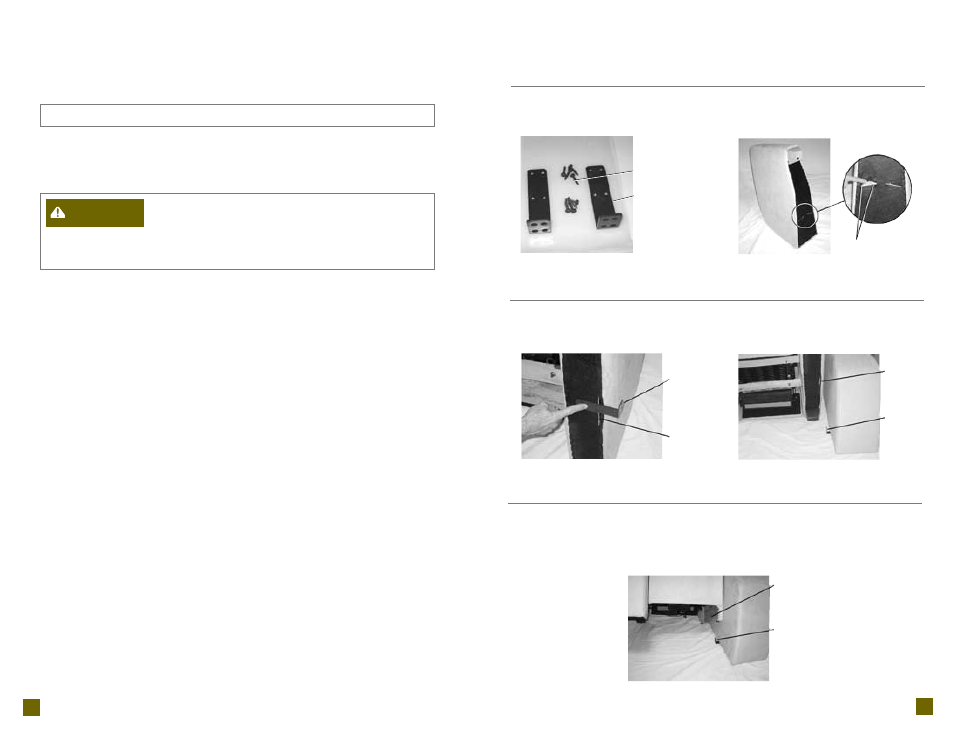
• The parts bag contains (8) pan head screws and (2) support brackets
(F
IGURE
1).
NOTE: Each unit comes with a par ts bag containing two suppor t brackets and
eight screws. Not all modular units will use both brackets.
3. Determine the location and quantity of support brackets to be used.
• The black frame cover on the bottom rail is cut in several places to
access the pilot holes and slots in the frame.
• The pilot holes are used to position the support brackets. The pilot holes
are located on both sides of the console, wedge and two arm recliner,
and on the arm side of the single arm recliner, reclining chaise and single
wedge recliner (F
IGURE
2).
• The support brackets fit in the frame slots to connect the modular units
(F
IGURE
4). The frame slots are located on both sides of the two arm
recliner and on the arm side of the single arm recliner, reclining chaise
and the single wedge recliner. The recliners have both pilot holes and
frame slots (F
IGURE
3).
• The support bracket is also used to hold the armless side of the single arm
units (F
IGURE
5).
• With the modular units rolled over, locate the pilot holes and frame slots.
Determine which sets of pilot holes need support brackets in order to
connect the modular units. A support bracket may be attached over the
frame slot if necessar y (F
IGURE
3).
TIP: Lay the suppor t brackets out and decide where they are needed before
attaching the brackets. Depending on your configuration, they may be needed
to fit in a frame slot or to hold the armless side of a single arm unit.
(Assembly Instructions Continued)
482 “Matinee” Home Theater
Assembly Instructions:
F
IGURE
1
F
IGURE
2
F
IGURE
5
F
IGURE
3
F
IGURE
4
482 “Matinee” Home Theater
Assembly Details:
Pilot Holes
Support
Bracket
Frame Slot in
Bottom Rail
Support
Bracket
Frame
Slot in
Bottom
Rail
Armless
Side
Support
Bracket
7
6
Pan Head
Screws
Support
Brackets
WARNING
Assembly Instructions for 482 “Matinee” Modular Units