Kontron KISS 4U Short KTQ67Flex User Manual
Page 31
8. Assembly, Disassembly
KISS 4U Short V2 – User's Guide (Version 1.01)
1
2
3
4
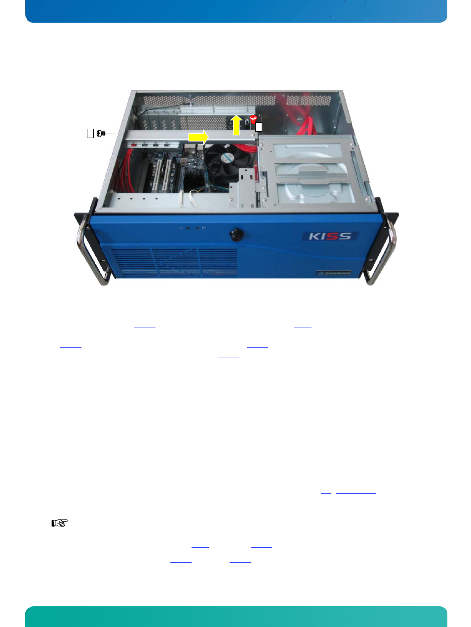
Fig. 29: Opened KISS 4U Short V2 platform - removing the card hold down brackets
5. Loosen (as shown in the Fig. 29 step 1 and 2), the internal fastening screw (Fig. 6, pos. 14) that secures the card hold
down bracket and the externally accessible fastening screw that secure the card hold down bracket to the chassis
(Fig. 21, pos. 4). Pull the card hold down bracket to the left (Fig. 29, step 3) to detach it from the sideways internal
mounted bolt. Lift the card hold down bracket out (Fig. 29, step 4). Put the card hold down bracket and the screws
aside for later use.
6. Install/remove the expansion card into/out of the expansion slot of the motherboard and fasten the slot bracket or
the expansion card bracket to the rear slot of the device.
7. Reinstall the card hold down bracket/s and secure it/them with the screws retained.
8. If required, mount the PCB holder to the corresponding positioning holes of the card hold down bracket using the
provided screws. Fix the upper edge of the expansion card into the notch of the PCB holder (height adjustable). Thus
the expansion card is firmly kept in place during high mechanical load (shock and vibrations).
9. In order to re-assemble the card hold down brackets, follow the steps in reversed order. Tighten the corresponding
screws half way at first. Then, tighten firmly the externally accessible screws. Only then tighten firmly the screws at
the notch that secure the card hold down bracket.
10. Close the KISS 4U Short V2 platform and secure the cover as described in the section 8.2 “Device Cover”.
The chassis of the KISS 4U Short V2 platform with attached cover is properly closed only, if the following
knurled screws are tightened:
the cover fastening screw (Fig. 9, pos. 13 and Fig. 24) on the front side
the knurled screws (Fig. 12, pos. 8 and Fig. 25)on the rear side.
www.kontron.com
29