Main specifications, Electrical specifications – Kontron KISS 2U Short KTQ67 User Manual
Page 43
12. Main Specifications
KISS 2U Short V2 – User’s Guide (V1.00)
12.
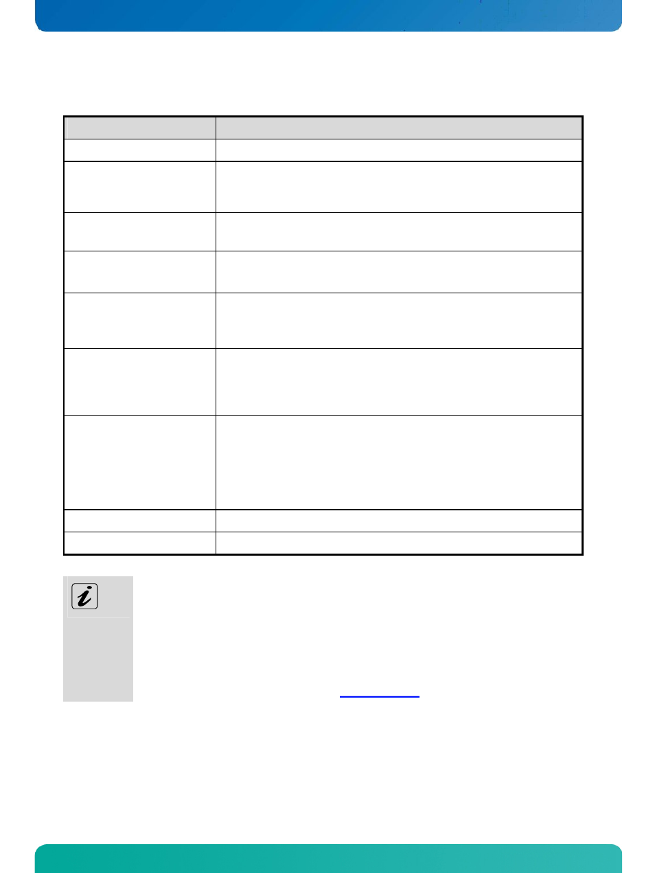
Main Specifications
KISS 2U Short V2-xxxxxxxx-y
Installed Board
*refer to “KISS 2U Short V2 Systems - Configuration Guides”
Control and
LED Indicators
(on the front side)
Power Button
Power LED (green)
HDD LED (yellow)
Interfaces
(on the front side)
2x USB (2.0)
Interfaces
(on the rear side)
Interfaces of the board slot
* refer to the manual of the installed board
Drive Bays
Up to two drive bays
* Optional configuration (depending on the system configuration ordered (refer
also to “KISS 2U Short V2 Systems - Configuration Guides”)
Free Expansion Slots for
KISS 2U Short V2 Low Profile
Up to four expansion slots, for low profile cards with max. card length of 230 mm:
2x PCI, 32 Bit @ 33 MHz
1x PCIe x16 (PEG)
1x PCIe x4
Free Expansion Slots for
KISS 2U Short V2
Up to two expansion slots, for full height cards with max. length of 230 mm:
2x PCI, 32 Bit @ 33 MHz
or
1x PCIe x16 (PEG) and 1x PCIe x4
or
1x PCIe x16 (PEG) and 1x PCI
Lithium Batterie
* refer to the manual of the installed board
Rated Voltage Range
Refer to the type label
KISS 2U Short V2 = System type
The “
xxxxxxxxx” group is replaced by up to a max. 8-digit combination of numbers, letter or space,
and represents the installed CPU board
The “
y” is replaced by a single letter (A through Z) representing the power supply installed into the
system.
The corresponding “KISS 2U Short V2 Systems - Configuration Guides” and the manual of the installed
board can be downloaded from our web site at
12.1. Electrical Specifications
The electrical specification you can read off on the type label of your KISS 2U Short V2 platform.
www.kontron.com
41