Vmp1 configuration – Kontron VMP1 with Netbootloader User Manual
Page 59
VMP1
Configuration
ID 26037, Rev. 01
Page 4 - 13
® 2002 PEP Modular Computers GmbH
4.3.4.9 Control Register
•
Bits 0 – 1: A “1” written to these bits lights the LED’s (LED1* is the green LED of
the top set on the front panel and LED2* is the red one)
•
Bits 2 – 3 are reserved
•
Bit S_RST: A “1” written to this bit initiates a Software Reset
•
Bits 5 – 6 are reserved
•
Bit 7: A “0” written to this bit configures the onboard SER connector to act as an
RS232 interface. A “1” written to this bit configures the onboard SER connector to
act as an RS485 interface (not optoisolated/half duplex)(default = 0)
4.3.4.10 Event Register
•
Bit WD is used to indicate that a watchdog overrun has occurred (logic 1 if
condition has occurred)
•
Bit 1 is reserved
•
Bit PB2 is used to indicate that the abort button has been pressed (logic 1 if this
condition has occurred)
•
Bits 3 - 6 are reserved
•
Bit 7: ”NOT LRST” – this bit shows the status of the LRST pin of the
TUNDRA UNIVERSE II (important for bootstrap loader).
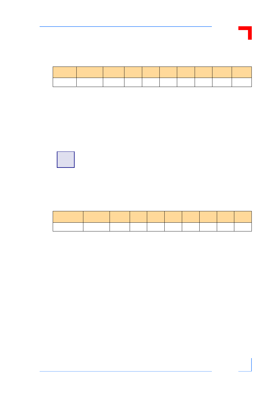
Table 4-14: Control Register
Register
Address
MSB
6
5
4
3
2
1
LSB
Control
FFe0 001a
RS_CTL
Res.
Res.
S_RST
Res.
Res.
LED2*
LED1*
!
Warning:
When setting bit 7 the user must ensure that the corresponding
interface is also an RS485. A mismatch will risk damage to the
VMP1 and/or the application.
Table 4-15: Event Register
Register
Address
MSB
6
5
4
3
2
1
LSB
Event
FFe0 001c
NLRST
Res.
Res.
Res.
Res.
PB2
Res.
WD