10 programming the board capability rom, 10 programming the board capability rom - 15, Configuration cp384 – Kontron CP384 User Manual
Page 61
ID 31440, Rev. 01
Kontron Modular Computers GmbH
P R E L I M I N A R Y
Rev
N
r. = CP384 -
31440_
01 - 060
503/
144
233
Page 4 - 15
Configuration
CP384
4.4.10
Programming the Board Capability ROM
The Board Capability ROM contains all the board data necessary to identify board, version, op-
tional features, etc., and to setup the basic software. The BCR is implemented using a 4 kbit
serial EEPROM of the type Microchip 93LC66.
(The contents list of the BCR is not described here.)
The serial interface of the device has been realized in hardware resulting in a very simple reg-
ister based programming interface with command, control, status and data registers. All proto-
col and serial timing specifications are resolved by hardware.
Programming of the BCR is undertaken as follows: The control word is written into the ROM
Control Register including command opcode and internal address. Then optional data (in case
of Write action) is written into the ROM Data Register. Command execution is started by setting
the Startbit in the ROM Command Register. Then Ready/Busy must be polled in the ROM Sta-
tus Register. After reaching Ready status, the next command can be set up and data (in case
of Read action) can be fetched from the ROM Data Register.
Table 4-19: Output Status Register
BITS
TYPE
DEFAULT
FUNCTION
31
r
0
Fail
30
r
0
Diag
29 - 0
r
0
Reserved
Table 4-20: Input IRQ Register
BITS
TYPE
DEFAULT
FUNCTION
31
r/w
0
Not used
30
r/w
0
Input compare interrupt enable
29 - 0
r/w
0
Input event interrupt enable
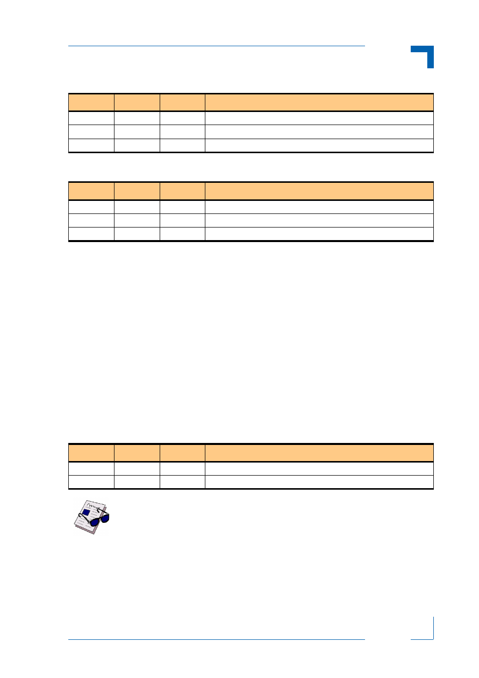
Table 4-21: ROM Command Register
BITS
TYPE
DEFAULT
FUNCTION
31
r/w
0
Startbit
30-0
r/w
00
Reserved
Note ...
The Startbit will be automatically reset as soon as an action is completed.