1 digital input and output interface, Digital input and output interface - 6, Functional description cp384 – Kontron CP384 User Manual
Page 36: Digin cluster digout cluster key, Page 2 - 6
Kontron Modular Computers GmbH
ID 31440, Rev. 01
P R E L I M I N A R Y
Re
vNr. = CP384
-
31440
_01 -
06
0503
/14
4228
Page 2 - 6
Functional Description
CP384
The connection for the external supply (+24V DC ± 20%) is realized by reserved/defined pins
within the output cluster at the front panel connector CON2.
At power up, all digital outputs are switched off (NC). In the course of operation they can be
collectively switched off, either by software (RESET) or by the application via the EXTRESET
signal to the CON2 connector.
2.7.1
Digital Input and Output Interface
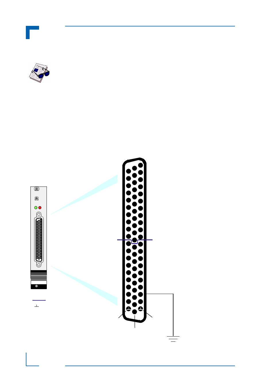
The digital input and output interface is routed through the CON2 connector. The following fig-
ure and table indicate the pin layout and pinout of this connector.
Figure 2-2: Pin Layout of the Digital Input and Output Interface Connector CON2
Note ...
The external power is supplied only to the relay coils. Within the CP384, the
external supply power is galvanically isolated from all digital output pins on
CON2
CP 383
RUN FAIL
Pin 1
Pin 22
Pin 43
+
15+
R
DIGIN
CLUSTER
DIGOUT
CLUSTER
KEY
R = Reset
+ = VCC
+
13-
13+
9-
15-
12+
5-
10-
7+
2+
11+
12-
0-
14+
9+
7-
6+
3-
5+
4-
6-
8+
0+
1-
3+
14-
11-
8-
10+
1+
2-
4+
C = relay common pin COM
NC = relay normally closed pin NC
NO = relay normally open pin NO
= GND
+
C
C
C
C
C
C
C
C
NC
NC
NC
NC
NC
NC
NC
NC
NO
NO
NO
NO
NO
NO
NO
NO
Channel 0
Channel 1
Channel 2
Channel 3
Channel 4
Channel 5
Channel 6
Channel 7