Introduction cp384 – Kontron CP384 User Manual
Page 27
ID 31440, Rev. 01
Kontron Modular Computers GmbH
P R E L I M I N A R Y
Rev
N
r. = CP384 -
31440_
01 - 060
503/
144
227
Page 1 - 11
Introduction
CP384
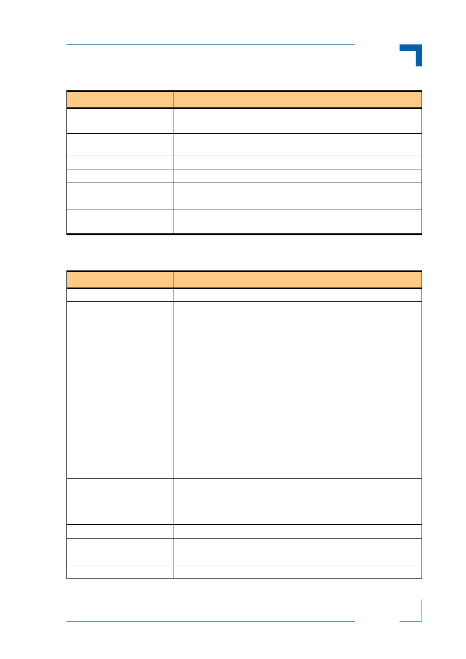
Table 1-4: CP384 Digital Input Specifications
TYPE
DESCRIPTION
Input Voltage Range
Low:
-3V to +5V
High: +11V to +30V
Channels
16 channels isolated from the system side. They do not share common GND
or VCC.
Channel Connections
2 pins per channel; differential input
Input Filter (edge frequency)
10 kHz
Input Protection
8 kV ESD
Isolation
2 kV process to system
Input Impedance
Minimum:
1.5 k ohm
Maximum: 6 k ohm at 30V
Table 1-5: CP384 Digital Output Specifications
TYPE
DESCRIPTION
Channels
8 channels of relay switched digital outputs grouped into one cluster
Channel Connections
Each channel is comprised of a single pole, double throw set of relay contacts:
• COM (common):
relay middle pole
• NO (normally open):
when the relay is switched off this pin is not con-
nected to the COM pin
• NC (normally closed): when the relay is switched off this pin is connected
to the COM pin
All relay contacts are routed to the front panel connector.
Within the CP384 each relay and its contacts are galvanically isolated from the
system and from the other relays and their contacts.
External Reset
All digital output channels of a cluster can be collectively switched to the
normally closed (NC) position by using one of the following methods:
• externally via the EXTRESET signal
• internally on request from the application via the DIO ProComm
controller
This results in all outputs being switched to the NC position irrespective of the
input data for these channels.
Switching Voltage Range
(Resistive Load)
The CP384 is designed to switch up to 250V DC/AC and up to 0.5A of current,
but the total power per contact being switched must be less then 15W.
A relay’s life time is about 2x10
6
switches at switching voltage 24V and
switching current 0.5A.
Switch Contact Resistance
< 50 milliohms
Switching Delay Time
T
on
= 3 ms ( typical at 24V )
T
off
= 2 ms (typical at 24V with no coil suppression)
Switching Bounce Time
T
bounce
= 3 ms (typical at 24V)