2 jumper settings, 1 cmos clear/hold jumper setting (jcc) – Habey PRO-6820 User Manual
Page 29
3.2 Jumper Settings
Please refer to the following jumper setting guide before installing your
hardware devices. Note: How to identify PIN1 of jumper and interface:
Please observe the word mark of plug socket, it will use “1” or bold line or
triangular symbols; and please look at the back of PCB. Each interface
weld spot has a square point, which is PIN 1. The PIN1 of all the jumpers
has a white arrow beside it.
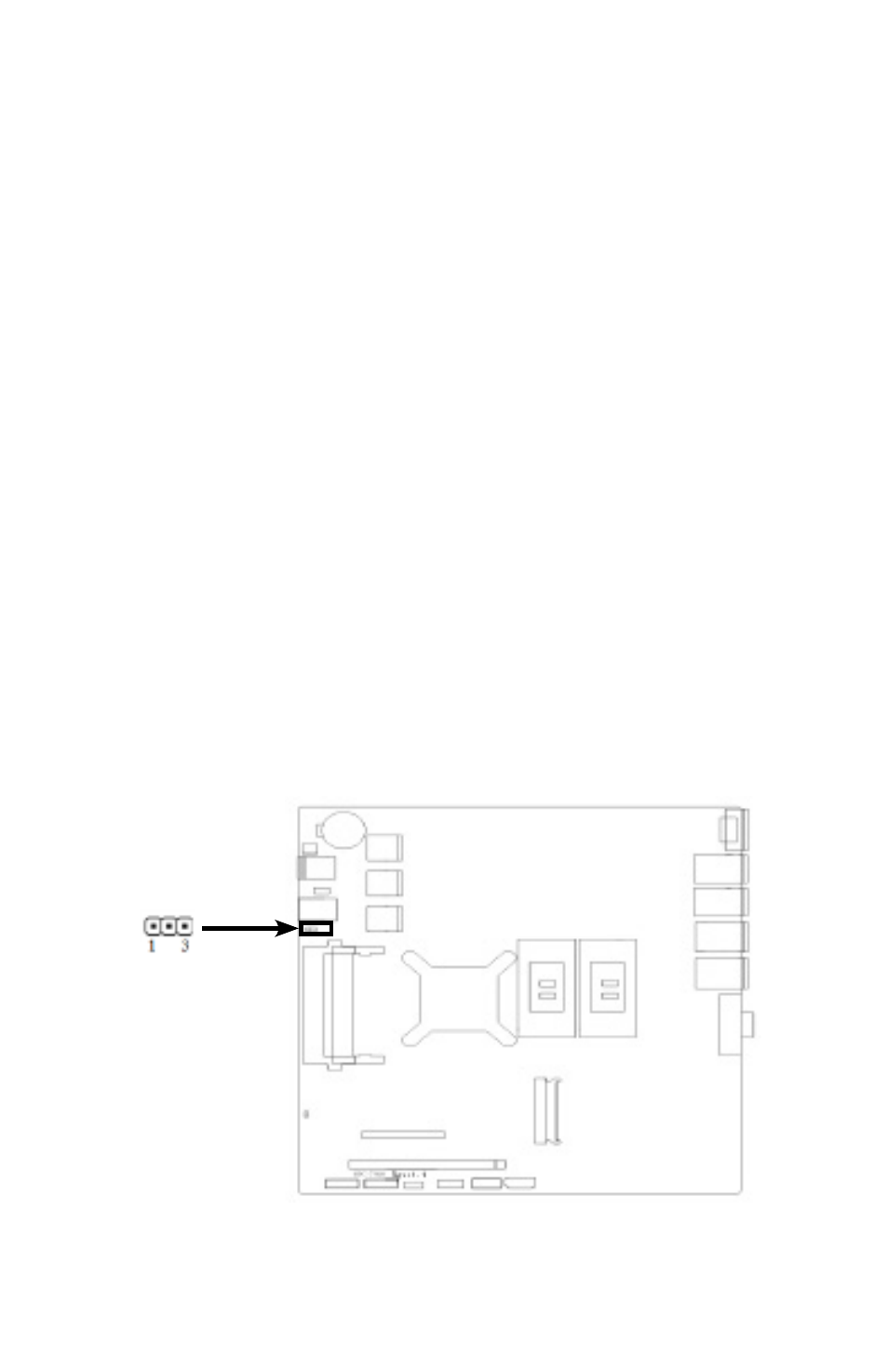
3.2.1 CMOS Clear/Hold Jumper Setting (JCC)
CMOS is powered by the onboard button cell. Clear CMOS will lead to
permanent elimination of previous system settings and back to the origi-
nal system setting (factory default).
Steps:
(1) Turn off the computer and disconnect the power supply
(2) Use Jumper Cap JCC Pin1-2 short for 10 sec(1-2). Then restore
the default setting with Pin2-3 connected(2-3)
(3) Turn on the computer, then press “DEL” key to enter BIOS setting
and reload optimal defaults.
(4) Save and Exit.
24