Elecraft P3SVGA User Manual
Page 8
8
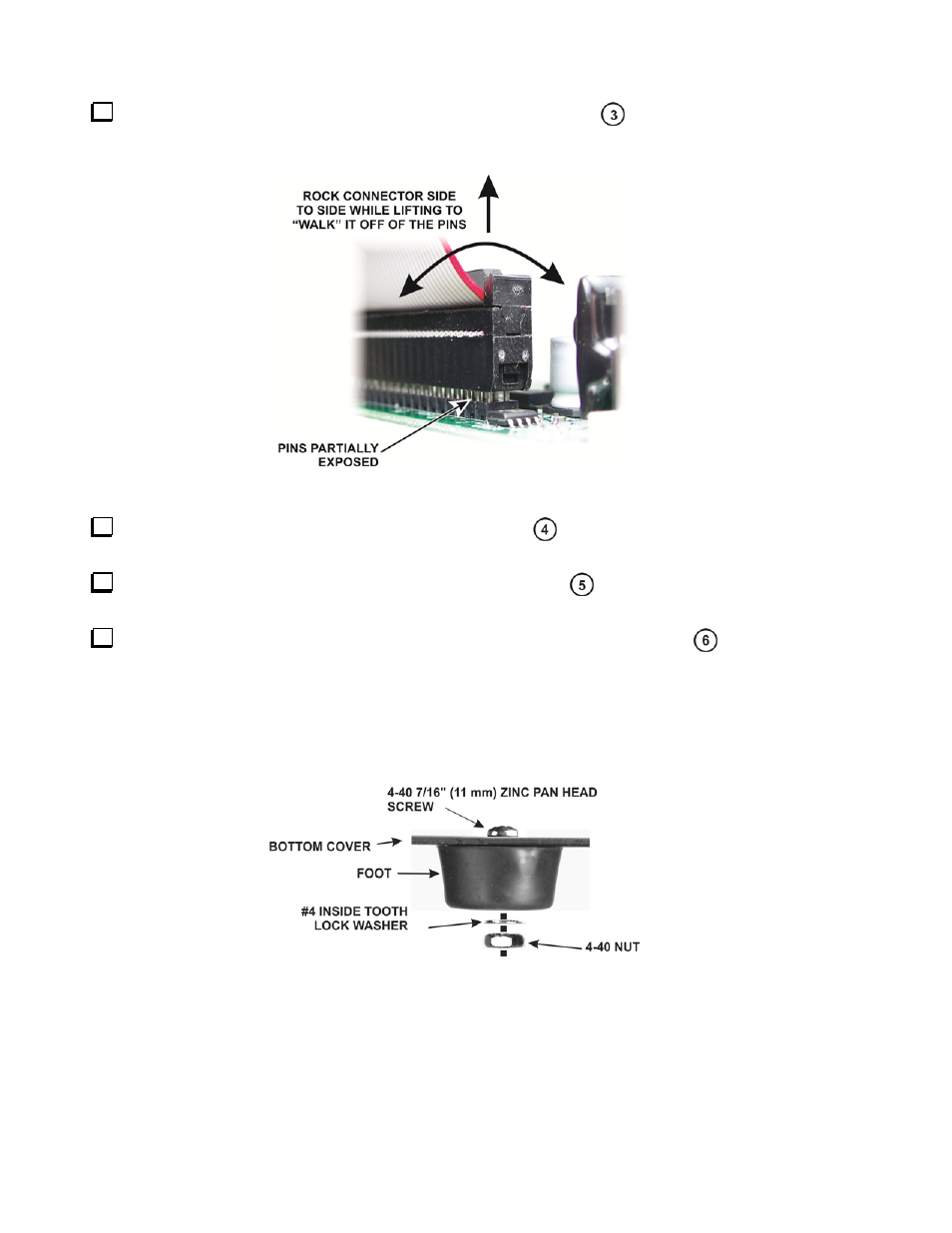
Lift the I/O board out of the P3 and unplug the ribbon cable (Figure 2
). Take care not to damage
the board. Hold the board while working the connector side to side to “walk” it off of the pins as shown in
Figure 3.
Figure 3. Unplugging the Ribbon Cable from the I/O Board.
Unplug the TMP coaxial cable from the RF board (Figure 2
). This is a friction-fit connector. Do
not pull on the black coaxial cable. Grip and pull only on the metal connector.
Remove the four screws holding the rear panel in place (Figure 2
) and lift the rear panel off of
the P3.
Remove and reverse the mounting hardware for both rear feet as shown in Figure 2
). Install the
hardware as shown in Figure 4.
INSTALLATION HINT: Put the washer and screw in the foot opening and press your finger over the
opening until the threads on the nut are caught by the screw. It may help to turn the unit over so gravity
helps. Once the nut is started pull the foot away from the bottom cover while tightening the screw. The
friction of the washer against the bushing inside the foot will keep the nut from turning as you tighten.
Figure 4. Reversing the Foot Hardware.