Checkout and calibration, Operation and applications – Elecraft AT1 41 dB Step Attenuator User Manual
Page 4
4
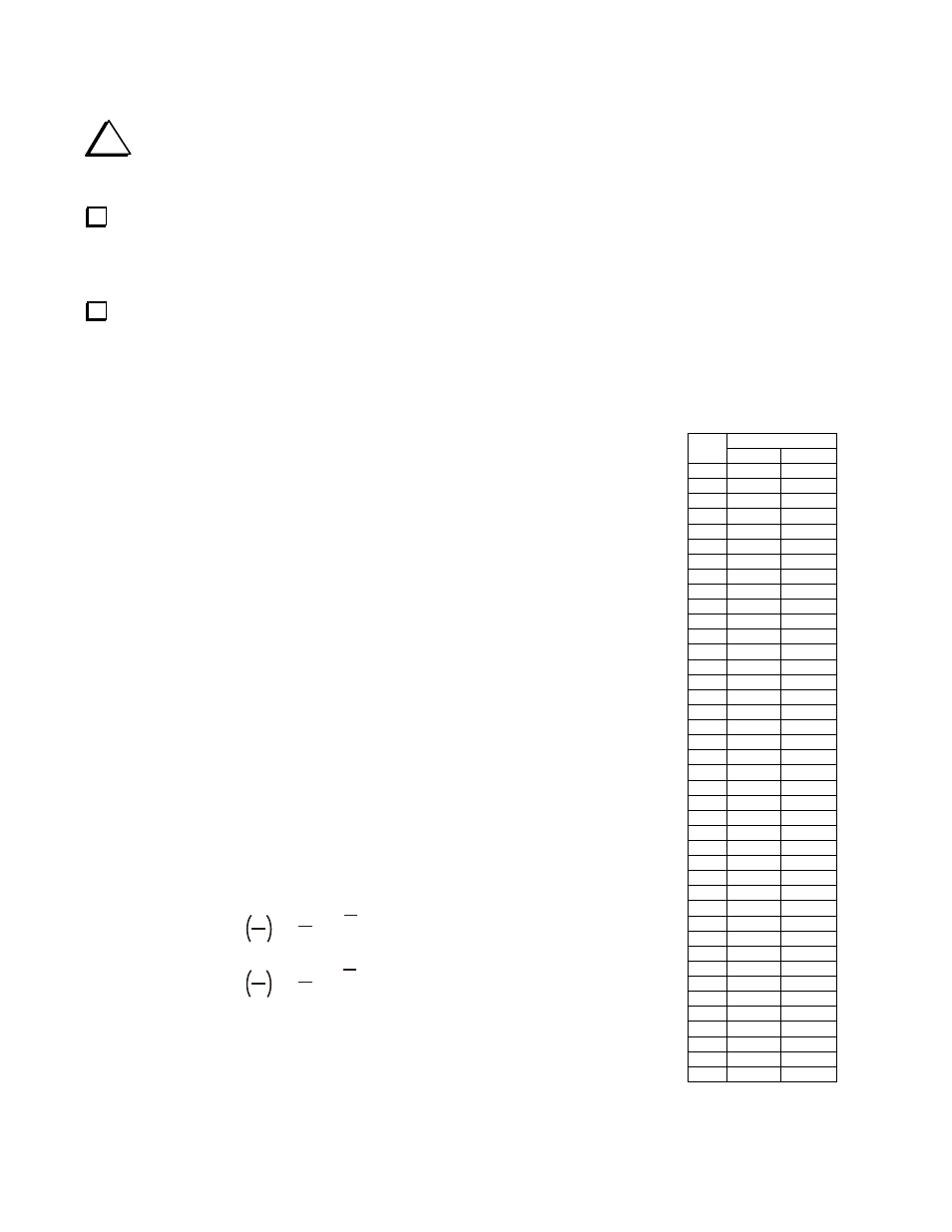
Table 1.
Decibel Conversion.
Ratio
dB
W E/I
1 1.3 1.12
2 1.6 1.26
3 2.0 1.41
4 2.5 1.58
5 3.2 1.78
6 4.0 2.00
7 5.0 2.24
8 6.3 2.51
9 7.9 2.82
10 10.0 3.16
11 12.6 3.55
12 15.8 3.98
13 20.0 4.47
14 25.1 5.01
15 31.6 5.62
16 39.8 6.31
17 50.1 7.08
18 63.1 7.94
19 79.4 8.91
20 100 10.0
21 126 11.2
22 158 12.6
23 200 14.1
24 251 15.8
25 316 17.8
26 398 20.0
27 501 22.4
28 631 25.1
29 794 28.2
30 1000 31.6
31 1259 35.5
32 1585 39.8
33 1995 44.7
34 2512 50.1
35 3162 56.2
36 3981 63.1
37 5012 70.8
38 6310 79.4
39 7943 89.1
40 10000 100.0
41 12589 112.2
i
Normally the BNC jacks J1 and J2 will be installed on top of the board within the silk screened outline.
However, if you are planning to use the AT1 in an enclosure, you may optionally mount J1 and J2 on the bottom of
the board or use connectors that orient the jacks perpendicular to the board (see Assembly Options on page 2).
Install BNC jacks J1 and J2. Note that there are extra ground solder pads provided for those who wish to mount the
jacks differently for use in an enclosure. Trim the two longer pins flush after soldering.
__ J1
⇒
__ J2
If desired, install the rubber feet on the bottom of the board. Separate the feet, then remove the protective backing from
each foot and place one at each corner on the bottom of the board.
Checkout and Calibration
The AT1 Step Attenuator requires no calibration. Its accuracy is fixed by the value of
the resistors used. You can confirm that you have all the resistors in the correct
positions by checking the resistance of each attenuator section as described under
Troubleshooting on page 5.
Operation and Applications
If you’ve not owned a good step attenuator before, below are a few examples of how it
can be immediately useful in your station.
General Operation
RF is applied to one BNC connector and the attenuated signal is available at the other
BNC connector. The AT1 is a symmetrical design for use in a 50 ohm impedance line;
either connector may be used as the input or the output. With all the switches in the up
(OUT) position there is no significant attenuation. You can select any level of
attenuation from zero to 41 dB in 1 dB steps by throwing a combination of switches to
the IN position and adding the dB values of each switch. For example, you can obtain
15 dB of attenuation by placing the 10 dB, 3dB and both 1 dB switches to IN
(10+3+1+1=15 dB).
The attenuation in dB represents a ratio. It indicates how much the signal at the output
has been attenuated relative to the input. The value in dB may be expressed as a ratio in
power, voltage or current. You can calculate these ratios using the formulas in Figure 3
or you can refer to Table 1. Table 1 shows the ratios for all levels of attenuation from
1 dB to 41 dB in 1 dB steps for power (W), or for voltage or current (E/I). For example,
if you apply 1watt of power to the AT1 and select 15 dB of attenuation, the power at the
output would be 1 watt divided by 31.6 = 0.0031 watts or 3.1 milliwatts. Conversely, at
15 dB the level at the input to the AT1 is 31.6 times larger than the output. If you are
comparing current or voltages, use the ratios in the E/I column.
dB = 10 LOG
dB = 20 LOG
B
A
B
A
B
A
B
A
or
or
= 10
dB
10
= 10
dB
20
where A and B are watts
where A and B are volts or amps
Figure 3. Decibel Formulas.
QRPp Operation
The 2-watt power capability of the AT1 makes it ideal for QRPp experimentation.
Simply connect the AT1 between the output of your 2-watt or less transmitter and the antenna or antenna tuner. With all the
switches in the up (OUT) position, there is no attenuation. Now you can reduce power by throwing the switches to IN. For