Elecraft AT1 41 dB Step Attenuator User Manual
Page 3
3
Solder joints should be clean and shiny. If a joint appears dull or has fine cracks, it is probably cold. Cold solder joints should
be cleaned and re-soldered. First, use solder wick (desoldering braid) to remove the old solder. Then apply fresh solder. If
you have many cold solder joints, it probably indicates that your soldering iron temperature is too low, or that the tip or
solder itself is defective.
i
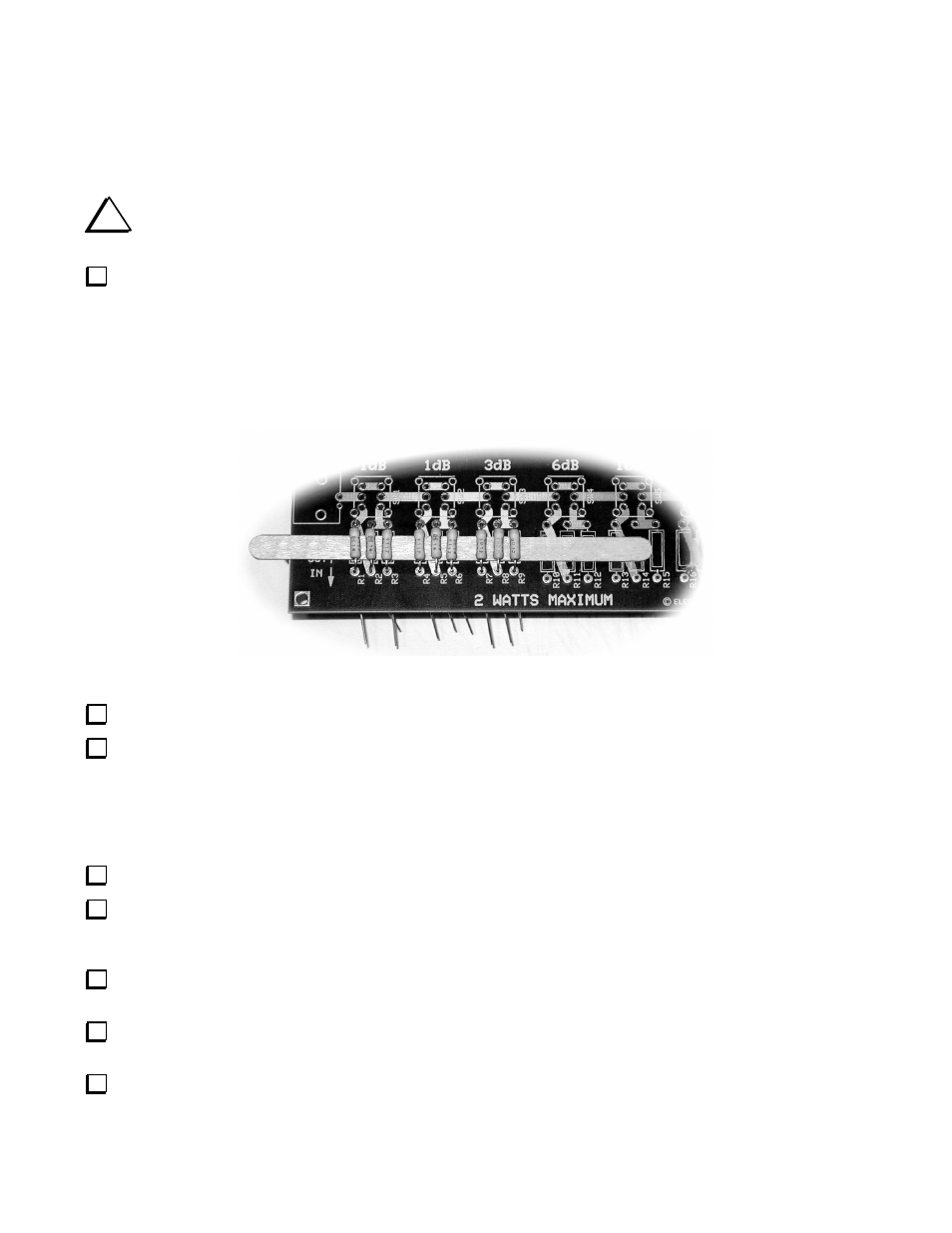
The resistors must be placed slightly above the board as described below so that cooling air can flow easily if
you operate the attenuator near its upper power limit.
Place the wooden spacer across the board between the solder pads for resistors R1 through R9, then position each
resistor on the board so it touches the spacer and spread the leads on the bottom to hold it in place (see Figure 2). Do not pull
the resistors tight against the wooden spacer. You’ll need to remove the spacer later. Working from left to right:
__ R1, 910Ω (911)
⇒
__ R2, 5.6Ω (5R6)
⇒
__ R3, 910Ω (911)
__ R4, 910Ω (911)
⇒
__R5, 5.6Ω (5R6)
⇒
__R6, 910Ω (911)
__R7, 300Ω (301)
⇒
__R8, 18Ω (180)
⇒
__R9, 300Ω (301)
Figure 2. Spacing Resistors Above the Board.
Solder each resistor and clip its leads flush with the bottom of the board.
Following the same procedure, reposition the wooden spacer between the solder pads R10 through R18 and install those
resistors.
__R10, 150Ω
⇒
__R11, 39Ω (390)
⇒
__R12, 150Ω
__R13, 100Ω
⇒
__R14, 68Ω
⇒
__R15, 100Ω
__R16, 62Ω
⇒
__R17, 240Ω
⇒
__R18, 62Ω
Remove the wooden spacer.
Position one of the slide switches in the outline next to the SW1 (1dB) marking on the board so the pins stick through
the solder pads. While holding the switch against the board, turn it over and touch one of the pins and solder pad with your
hot iron carrying a fresh drop of solder to tack-solder the switch in place.
Inspect the switch to ensure the pins on all four corners have their shoulders sitting flush against the board. If necessary
heat the tack-soldered pin while pressing down on the switch to position it against the board.
When you are satisfied with the switch position, solder the nine remaining pins, then go back and solder the first pin
properly.
In the same manner, install the remaining slide switches:
__ SW2: 1 dB
__ SW3: 3 dB
__ SW4: 6 dB
__ SW5: 10 dB
__ SW6: 20 dB