Elecraft T1 ATU Owner's Manual User Manual
Page 8
8
Remote Control
J3 on the T1 has two signals: DATA (tip) and TUNE (ring). This section explains how to use them to
control the T1 from a transceiver, computer, or other device. Note: If you place the tuner where you can’t
see its LEDs or hear its relays, you’ll need an SWR bridge to verify the T1’s matching progress. During
tuning, SWR will vary rapidly. Once SWR has stabilized for a few seconds, you can stop transmitting.
Using the TUNE Signal
An external PWR/TUNE switch (or a low-going signal from an open-collector or open-drain driver) can be
connected to J3-ring. Pulling this line to ground for about 1/2 second will enable auto-tuning just as if you
pressed the T1’s TUNE switch. The cable supplying the TUNE signal to the T1 should be well-shielded;
small coax such as RG-174 can be used in most cases. If you use also use the DATA line (see below),
you’ll need cable with two conductors as well as a shield, such as Belden type 1508A.
Using the DATA Signal
DATA (J3-tip) is a bidirectional logic input. After the T1 is activated by the TUNE signal, it will request
band information via the DATA line. If valid band data is received, the tuner will store and recall network
settings on a per-band basis. This is very convenient since the tuner will then track band changes at the rig
without the need to transmit. If the tuner sees a TUNE signal but does not receive band data, it will revert to
default operation, i.e. no per-band storage. (Band IDs for 160-6 meters are 1-11. An ID of 0 is ignored, and
an ID of 12 sets L and C to 0. You can verify the band ID received by the T1 using INFO; see page 7.)
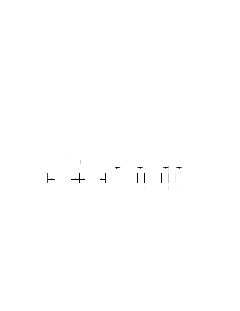
Figure 3 shows the protocol. First, the T1 sends a band request pulse on the DATA line, which is initially
an input at the control device. When the control device sees the end of the request pulse, it sets up DATA
as an output, and after a 10-ms delay, sends a band ID to the T1 (band 6 in this example, or “0110” in
binary). The ID is sent most-significant-bit (MSB) first, each bit having a high and low period. The high
period is 4 ms for a “1” and 1.5 ms for a “0”. The low period is always 1.5 ms, except for that of the LSB
(least-significant-bit), which can be extended indefinitely. Timing values should be held to +/- 15%.
50 ms
4 ms
1.5 ms
"0"
"1"
"1"
"0"
MSB
LSB
10 ms
T1 Data TX
T1 Data RX
Figure 3