Elecraft K144XV Ref Lock Manual User Manual
Page 9
9
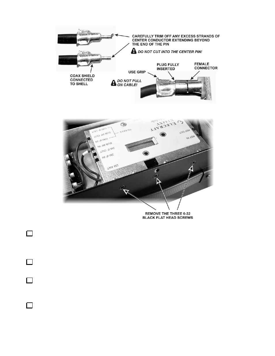
Figure 5. TMP Cable Connectors.
Figure 6. Freeing the K144XV Module (Optional).
If you removed the three 6-32 black flat head screws to free the K144XV module, replace them and verify
that all the TMP cables are still fully seated in their connectors.
Installing the Firmware and Testing the Board
Plug the Serial Cable connector into the RS232 connector on the K144XV module. Connect the other end to
your computer and run the K144XV Utility program.
Turn on your K3 while watching the STATUS LED on the K144XV module. It should flash once or twice,
indicating normal operation and that it is ready for firmware. (If the STATUS LED remains on, the K144XV
module MCU has failed to initialize properly. See Status Light in your K144XV manual for assistance.)
Using the Utility program, start the download. The STATUS LED should flash repeatedly indicating it is
loading new data from the Utility program.
- KX3 Owner's Manual (58 pages)
- KX3 Assembly Manual (47 pages)
- KX3 Assembly Manual Errata (5 pages)
- KX3-2M (30 pages)
- KX3-PCKT (2 pages)
- KX3 Mobile Installation And Operation Guide (17 pages)
- KX3 Guide for Blind Operators (7 pages)
- KX3 Quick Reference (2 pages)
- K3 Programmers Reference (26 pages)
- KX3 Speaker Grille Instructions (9 pages)
- KXFL3 Filter Option (12 pages)
- KXFL3 Filter Option Errata (2 pages)
- KXAT3 (5 pages)
- KXBC3 (13 pages)
- KXPD3 (4 pages)
- Proset Boom Headset (1 page)
- PX3 Owner's Manual (53 pages)
- PX3 Owners Manual Errata (2 pages)
- KXPA100 Manual (55 pages)
- KXPA100 Assembly Manual (27 pages)
- KXPA100 Assembly Errata (1 page)
- KXPA100 Programmers Reference (24 pages)
- KXAT100 Installation Manual (17 pages)
- KX1 Manual (96 pages)
- KXAT1 (12 pages)
- KXPD1 (7 pages)
- KXB30 (8 pages)
- KXB3080 (20 pages)
- K1 (91 pages)
- K1 1.09 F/W (1 page)
- KNB1 Manual (8 pages)
- KAT1 Manual (15 pages)
- KFL1-2 (2 pages)
- KTS1 (1 page)
- KBT1 Manual (8 pages)
- KBT1 Manual Errata (2 pages)
- K1BKLTKT LCD Mod Kit (6 pages)
- K2 Owner's Manual (171 pages)
- K2 Owner's Manual Errata (1 page)
- K2 PLL (4 pages)
- K2ATOBKIT (15 pages)
- K2ATOBKT (2 pages)
- K2 Keying Modification Instructions (4 pages)
- KPA100 Manual (74 pages)
- KPA100 Shield Upgrade (3 pages)