Replace all the screws – Elecraft K144XV Ref Lock Manual User Manual
Page 10
10
When the download is complete, turn the K3 off, wait at least 10 seconds, and then turn it on again while
watching the STATUS LED. Verify that the STATUS LED flashes once or twice and then turns off, indicating
normal operation.
At the Utility Command Tester screen, type B followed by enter. The K144XV should respond with B001;
indicating that the Phase Lock Board is responding. If the Phase Lock Board is not working the K144XV will
respond with B000; If that occurs, carefully check the cable connections.
Uplug the RS232 cable from the K144XV, turn the K3 off and disconnect power.
Replacing the Top Cover
Replace the chassis stiffener bar using two 4-40 3/16” (4.8 mm) black flat head screws at the ends. If the
KPA3 is installed, attach the stiffener to the shield using two 4-40 1/4” (6.4 mm) screws with lock washers
under the screws. (Some stiffener bars do not have threaded PEM nuts attached. In that case, secure the screws
with 4-40 nuts and place the lock washers under the nuts).
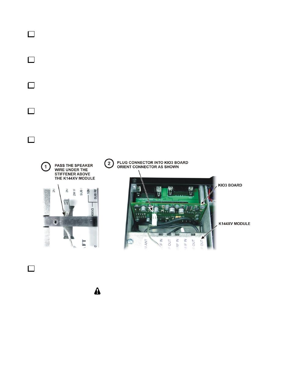
Hold the top cover above the K3, route the speaker wire under the stiffener bar. Route it under the stiffener
bar at the depression in the top of the K144XV module as shown in Figure 7 and plug it into P25 on the KIO3
board at the left rear of the K3.
Figure 7. Connecting the Speaker Cable.
Position the top cover on the K3. Note that the tab on the back center goes under the rear lip of the K3 rear
panel. Secure the top cover with the nine 4-40 3/16” (4.8 mm) black flat head screws you removed earlier (see
Figure 1 on page 6 for the screw locations).
REPLACE ALL THE SCREWS!
The K3's chassis has excellent rigidity despite its light weight. The screws that hold the top
cover in place are an important part of the structural design. Please be sure to replace all the
screws and verify they are tight whenever you replace the cover or other panels