Elecraft K144XV Ref Lock Manual User Manual
Page 8
8
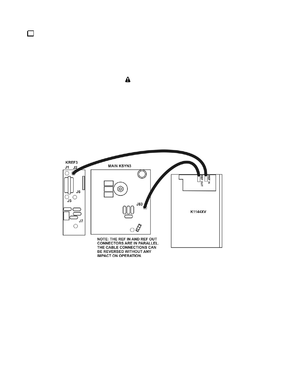
Connect the TMP cables as shown in Figure 4. The TMP cables are simple friction-fit connectors but must
be properly aligned when inserted (see Figure 5). Disconnect the TMP cable from J2 on the KREF3 board and
plug it into the
REF OUT
TMP connector on the Phase Lock board. Handle the cable carefully to avoid
unplugging it from J83 KSYN3 board below the K144XV module. It’s a good idea to put on finger on the cable
at J83 to keep it in place while moving the cable. If it does come loose, use a pair of needle nose pliers or heavy-
duty tweezers to replace it, gripping the connector by the metal part, or temporarily loosen the K144XV module
so it can be moved as described in Note 1 below to reach the connector with your fingers.
NOTES
:
1) If you are having difficulty inserting the TMP cables into the REF IN and REF OUT
connectors, you can remove the three 6-32 black flat head screws that hold the K144XV
module in place (see Figure 6). That will free the module so you can lift the end to better
access the TMP connectors. Take care that you do not pull the other TMP connectors loose
while doing this.
2) The
REF IN
and
REF OUT
connectors are electrically in parallel so the
REF IN
and
REF OUT
cable connections may be reversed with no impact if it’s easier to do so.
Figure 4. TMP Cable Connections.