Figure 5 paper washer – Elecraft K2VCOSHLDKT User Manual
Page 3
Page 3
Look closely at T5’s leads where they exit the holes on the bottom side. The leads must have no enamel residue, and should be
tinned so that they appear clean and shiny. If not, remove T5 and prepare the leads as described earlier.
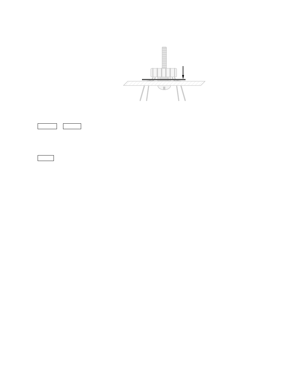
Place the paper washer over T5 as shown in Figure 5. Push downward gently on T5’s leads until the washer lays flat.
Figure 5
Paper washer
Solder and trim T5’s leads.
Connect a power supply to the K2 and turn it on.
Use BAND + or BAND - to select the 80-meter band, and set the VFO for a frequency of about 4000.10 kHz.
Connect the frequency counter probe to the VCO test point, TP1. Activate the counter using CAL FCTR in the menu.
You should now see a frequency counter reading in the 8 to 10 MHz range. It may or may not be stable at this time (i.e., the
frequency may be changing). If the reading is 0000 kHz or is changing rapidly, you probably don’t have the counter cable
connected to the VCO test point, or T5 may not be properly wound or soldered.
Tap MENU to exit CAL FCTR.
Disconnect the internal frequency counter probe and remove it completely from the K2.
Connect a DMM (digital multimeter) to the left end of resistor R30 (near the center of the synthesizer area of the RF board) and
ground. Use a small alligator clip to ensure a good connection. Select the DMM’s 20 or 30-volt DC voltage scale.
On each band, set the VFO to the low/high frequencies listed the in table below, and record (in pencil) the DC voltages at R30.
Band
Low Freq.
Voltage
High Freq.
Voltage
160 m
1800
______
2000
______
(If K160RX option is installed)
80 m
3500
______
4000
______
60 m
5300
______
5450
______
(If K60XV option is installed)
40 m
7000
______
7300
______
30 m
10000
______
10150
______
20 m
14000
______
15000
______
17 m
18000
______
18200
______
15 m
21000
______
21450
______
12 m
24800
______
25000
______
10 m
28000
______
28800
______
If some VCO control voltage readings above are less than 1.0 V, or some of them are greater than 7.5 V, you’ll need to shift the
entire set of readings so that they are all within this range. First, switch to the band (and frequency) that had the highest or
lowest voltage. Next, squeeze or spread the turns on T5’s 1-2 winding slightly to bring that reading into range. (Squeezing the
turns closer together increases the inductance; spreading them out decreases the inductance.) Finally, re-measure all of the
voltages to make sure they're in range. Note: In rare cases, you may have to re-wind T5, adding or removing one turn. If you
cannot spread the turns far enough apart, remove one turn. If you cannot squeeze the turns together tightly enough, add one turn.
Disconnect the DMM from R30.
Turn the K2 off and disconnect the power supply.