Top side of rf board figure 3 figure 4 – Elecraft K2VCOSHLDKT User Manual
Page 2
Page 2
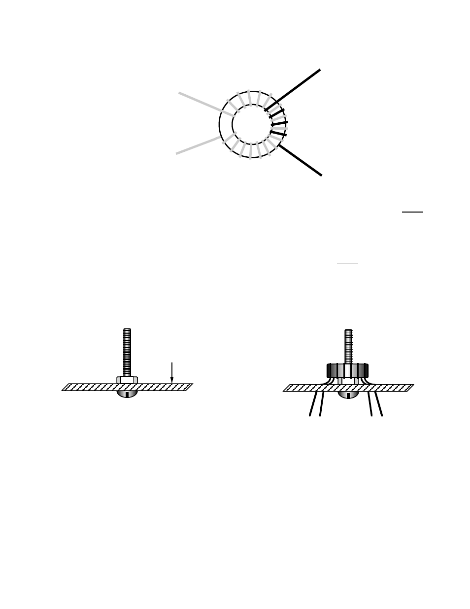
Locate the T37-6 core (yellow), which is smaller than the original T50-6 core. It will be used to wind a new T5. As shown in
Figure 2, T5 will have two windings, identified as leads 1-2 (red wire) and 3-4 (green wire).
Figure 2
Green,
4 turns
1
2
3
4
Red,
17 turns
Cut a 14-inch (35 cm) length of red enamel wire, and an 8-inch (20 cm) length of green.
For the 1-2 winding, use 17 turns of red enamel wire. (Each pass through the core counts as one turn.) Wind the wire tightly
against the core. Leave the leads at least 1” (2.5 cm) long, and do not strip the enamel insulation off yet.
Examine the 1-2 winding closely. As shown in Figure 2, lead #2 must exit from below the core, and lead #1 from above the
core. If this is not the case, remove the wire and correct the winding sense.
Distribute the 17 turns of the 1-2 winding evenly over about 90% of the core as shown.
For the 3-4 winding, use 4 turns of green enamel wire, positioned as in Figure 2. Wind the wire tightly against the core. Leave
the leads about 1” (2.5 cm) long and do not strip them yet.
Examine the 3-4 winding for correct sense as you did for the 1-2 winding. Lead #4 must exit from below the core.
Trim all four leads of T5 to about 1 inch (2.5 cm) long.
Referring to Figure 3, insert the 5/8” (16 mm) nylon screw through the hole at the center of T5 from the bottom side of the RF
board. Secure the screw to the RF board using a nylon hex nut on the top side.
Top side of RF board
Figure 3
Figure 4
Install T5 temporarily (Figure 4), inserting the leads into their numbered pads on the RF board. The nylon screw should pass
through T5. Press down until T5 rests on the nylon nut.
Pull the leads through on the bottom, leaving a small amount of slack on the top as shown in Figure 4. The reason for the slack
is to accommodate the paper insulating washer, which will be added in a later step (see Figure 5, next page).
Using a black felt pen, mark the point on each lead where it enters its pad on the top side of the board. Then remove T5.
Remove the insulation from T5’s leads up to approximately the marked locations, then tin the leads. The enamel wire is heat-
strippable, so this can be done using a soldering iron. Additional information on stripping toroid leads can be found in the
“Assembly, Part II” section of your K2 owner’s manual; see Stripping Toroid Leads (page 54 in the latest revision).
Re-install T5 (see Figure 4).