Elecraft K60XV Manual User Manual
Page 12
12
Transverter Connector Installation
You can use either the original top cover XVTR IN/OUT holes (not applicable if you have a KPA100
installed), or phono jacks on the lower rear panel/heatsink. Both installations are covered below.
1. If you'll be using the original XVTR IN/OUT connectors on the top cover (BNC):
Remove any masking tape from the BNC holes in the top cover. If the inside surface is painted,
scrape or sand away sufficient paint for the connectors to make good contact.
Install BNC connectors in the XVTR IN and OUT holes, including the supplied solder lugs.
Cut two 4" (10 cm) lengths of RG174 coax cable.
At each end of the coax cables, remove 1/2" (13 mm) of the plastic jacket. Separate the braid from
the center conductor using a small, pointed tool. Cut away about half the strands, then twist together
and tin the remaining strands. Also twist and tin the strands of the center conductor.
Solder one end of a coax cable to the OUT jack (center conductor to the center pin, and shield to
the solder lug). Solder one end of the other coax cable to the IN jack.
Solder the free ends of the two coax cables to the pads of J1 on the top side of the K60XV board:
__ OUT center pin to J1 pin 1, shield to J1 pin 2 __ IN center pin to J1 pin 4, shield to J1 pin 3
Make sure that the coax cable shield wires are not touching any component leads.
2. If you'll be using phono jacks on the lower rear panel/heatsink:
Remove any masking tape from the phono jack holes in the heatsink. If the inside surface is
painted, scrape or sand away sufficient paint for the connectors to make good contact.
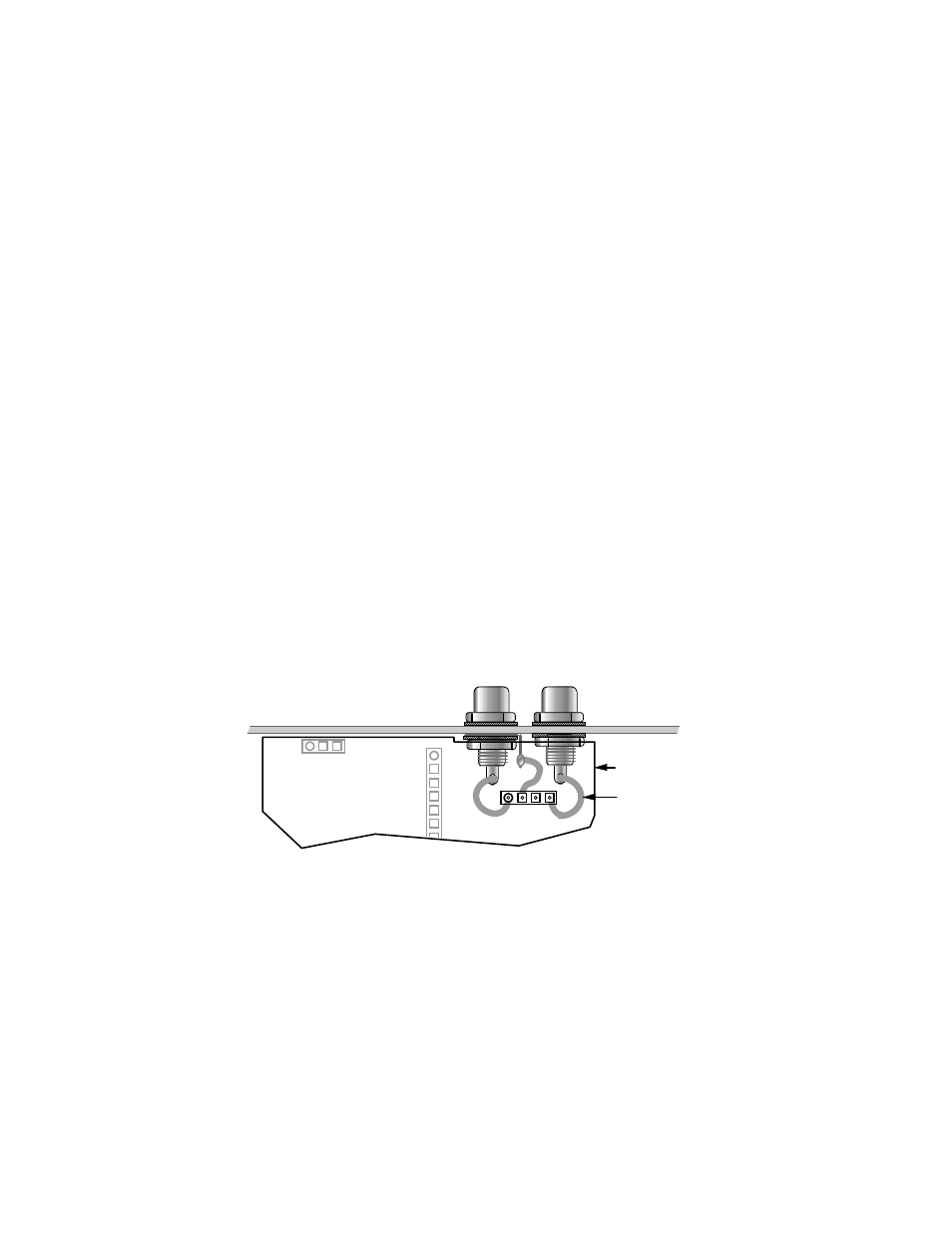
Install phono jacks in the XVTR holes in the heatsink, using 1/4" lock washers inside and outside.
(see drawing below). Use a solder lug on the left connector only, folding the lug away from the panel.
Note: These jacks can be tightened from the rear of the panel due to their hex-shaped flanges.
Prepare three 1" (25 mm) jumpers using #24 stranded hookup wire (black insulation). Strip 1/8"
(3 mm) of insulation from each end. Twist the strands together, then tin them very lightly.
Solder one wire to each phono jack as shown. Solder the third wire to the lug.
To see the location of the K60XV module relative to the two jacks, plug it in temporarily (P2 to
J15 on the RF board, P1 to J13). Unplug it and tilt its front edge upward to gain access to the pads of
J1. Insert the free ends of the three wires into the K60XV PC board at J1 pins 1, 2, and 4 as shown,
from the bottom side. Then fold the K60XV downward to gain access to the top side, and solder.
K60XV
PC Board
OUT
IN
1
P2
P1
(P2 and P1 are on
bottom of PC board)
Wires routed to J1
from underneath
2
4
2